Operating Instructions – Electronic Motor DRC.-..-DAC
15
3
Electronics
Unit Structure
3.4
Electronics
3.4.1
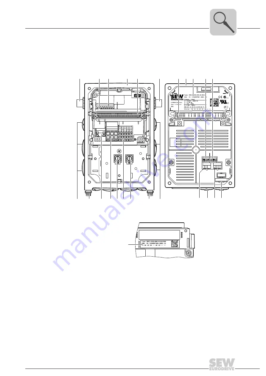
DRC electronics cover (inside) and connection box
The following figure shows the connection box and the bottom side of the DRC electron-
ics cover:
4762857739
[1]
AS-Interface connection
[2]
Nameplate of drive unit, see following detailed view
4853289611
[3]
AS-Interface terminals (wired to plug connector)
[4]
Connection box
[5]
Plug connector connection unit for DRC electronics cover
[6]
AS-Interface sensors
[7]
DRC electronics cover
[8]
Electronics cover nameplate
[9]
DIP switches S1/1 – S1/4
[10] DIP switches S2/1 – S2/4
[11] Cable glands
[12] Screws for PE connection
[13] Braking resistor connection
[14] Line connection L1, L2, L3
[15] Electronics terminal strips
[16] Switch t1 for integrator ramp (green)
[17] Diagnostic interface (underneath the gland)
[18] Setpoint switch f2 (white)
[19] Setpoint potentiometer f1 with screw plug
34567
34567
ON
ADE04SA
1
2
3
4
ON
ADE04SA
1
2
3
4
t1
S1
S2
f2 f1
1 2 3 4
1 2 3 4
[4]
[2]
[3]
[12] [15]
[11]
[14]
[12]
[12]
[12]
[16] [17] [18] [19]
[11]
[13]
[1]
[6]
[5]
[10]
[9]
[7]
[8]
[5]
[2]

