Operating Instructions – Electronic Motor DRC.-..-DAC
153
9
Function modules
Communication with AS-Interface Double Slave GLK31A
Function module
1
hex
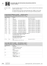
Cyclic operation with function module 1
hex
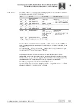
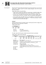
allows for selecting 6 fixed setpoints and for
extended error diagnostics.
The output data during the operation with function module 1
hex
correspond to the output
data during operation with function module 5
hex
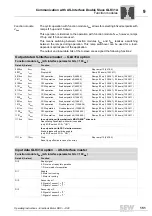
. The input data during operation with
function module 1
hex
are interpreted as different status codes.
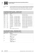
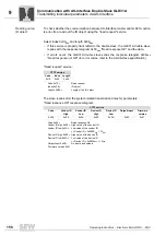
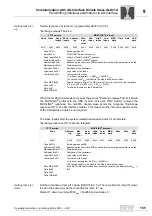
Output data AS-Interface master
→
GLK31A option
Function module 1
hex
(AS interface parameter bits = 001
bin
)
Data bit (A-slave)
Function
0000
bin
0
dec
Stop
Stop ramp t13 (
8476.0
)
0001
bin
1
dec
Stop/inhibit
Ramp t11 down (
8808.0)
0010
bin
2
dec
CW operation,
fixed setpoint n0 (
8489.0
)
Ramps t11 up (
8807.0)
, t11 down (
8808.0)
0011
bin
3
dec
CCW operation,
fixed setpoint n0 (
8489.0
)
Ramps t11 up (
8807.0)
, t11 down (
8808.0)
0100
bin
4
dec
CW operation,
fixed setpoint n1 (
8490.0
)
Ramps t11 up (
8807.0)
, t11 down (
8808.0)
0101
bin
5
dec
CCW operation,
fixed setpoint n1 (
8490.0
)
Ramps t11 up (
8807.0)
, t11 down (
8808.0)
0110
bin
6
dec
CW operation,
fixed setpoint n2 (
8491.0
)
Ramps t11 up (
8807.0)
, t11 down (
8808.0)
0111
bin
7
dec
CCW operation,
fixed setpoint n2 (
8491.0
)
Ramps t11 up (
8807.0)
, t11 down (
8808.0)
1000
bin
8
dec
CW operation,
fixed setpoint n3 (
1096.31
)
Ramps t11 up (
8807.0)
, t11 down (
8808.0)
1001
bin
9
dec
CCW operation,
fixed setpoint n3 (
1096.31
)
Ramps t11 up (
8807.0)
, t11 down (
8808.0)
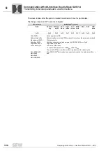
1010
bin
10
dec
CW operation,
Fixed setpoint n4 (
10096.38
)
Ramps t11 up (
8807.0)
, t11 down (
8808.0)
1011
bin
11
dec
CCW operation,
Fixed setpoint n4 (
10096.38
)
Ramps t11 up (
8807.0)
, t11 down (
8808.0)
1100
bin
12
dec
CW operation,
fixed setpoint n5 (
10096.39
)
Ramps t11 up (
8807.0)
, t11 down (
8808.0)
1101
bin
13
dec
CCW operation,
fixed setpoint n5 (
10096.39
)
Ramps t11 up (
8807.0)
, t11 down (
8808.0)
1110
bin
14
dec
In conjunction with mechatronic MOVIGEAR
®
drive unit:
Deactivating DynaStop
®
without drive enable signal (only when DIP switch S1/2 = "ON")
In conjunction with DRC electronic motor:
Releasing the brake without drive enable signal (only when DIP switch S1/2 = "ON")
1111
bin
15
dec
Stop
Reset (only effective in case of an error)
Stop ramp t13 (
8476.0
)
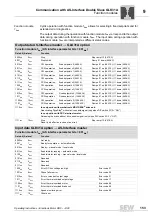
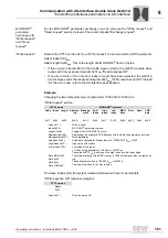
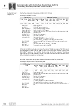
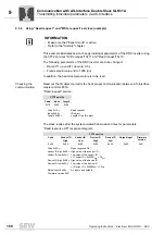
Input data GLK31A option
→
AS-Interface master
Function module 1
hex
(AS interface parameter bits = 001
bin
)
Data bit (A-slave)
Function
0000
bin
0
dec
Not ready
0001
bin
1
dec
Ready for operation – automatic mode
0010
bin
2
dec
Ready – manual mode / local mode
0011
bin
3
dec
Enable/motor running – automatic mode
0100
bin
4
dec
Enable/motor running – manual mode / local mode
0101
bin
5
dec
Reserved
0110
bin
6
dec
Reserved
0111
bin
7
dec
Reserved
1000
bin
8
dec
Error, DC link voltage too high
Error code 07
1001
bin
9
dec
Phase failure error
Error code 06
1010
bin
10
dec
Error, overcurrent output stage
Error code 01
1011
bin
11
dec
Error, thermal overload output stage
Error code 11
1100
bin
12
dec
Error, thermal overload motor
Error code 84
1101
bin
13
dec
Error, thermal overload brake coil
Error code 89
1110
bin
14
dec
Speed monitoring error
Error code 08
1111
bin
15
dec
Other error

