Operating Instructions – Electronic Motor DRC.-..-DAC
189
11
Description of status and operating displays
Service
11.5 Description of status and operating displays
11.5.1 LEDs
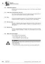
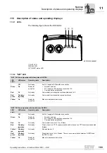
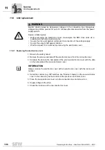
The following figure shows the DRC LEDs:
11.5.2 "NET" LED
9007201629456907
[1] NET LED
[2] RUN LED
[3] "DRIVE" status LED
NET RUN DRIVE
[1]
[2]
[3]
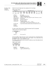
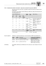
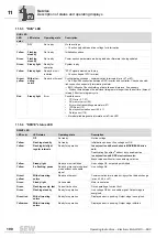
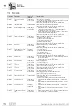
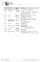
"NET" LED in conjunction with binary slave GLK30A
LED
color
LED status
Operating state
Description
-
Off
Not ready
No 24 V supply at AS-Interface connection
Green
On
Ready for
operation
•
Normal operation
•
24 V supply at AS-Interface connection OK
•
Communication established
Red
On
Not ready
Communication interrupted or slave address set to 0
Red/
green
Flashing
regularly
Not ready
Communication interrupted or peripheral error
Yellow
On
Ready for
operation
Manual mode/local mode active
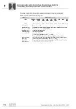
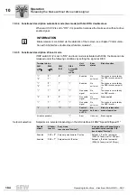
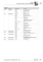
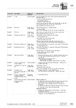
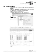
"NET" LED in conjunction with double slave GLK31A
LED
color
LED status
Operating state
Description
-
Off
Not ready
No 24 V supply at AS-Interface connection
Green
On
Ready for
operation
•
Normal operation
•
24 V supply at AS-Interface connection OK
•
Communication established
Red
On
Not ready
Communication error at A- or B-slave
Red
Flashing
regularly
Not ready
Protocol error, no CTT3 communication with A-slave or no CTT2 communication with
B-slave
Yellow/
red
Flashing
regularly
Not ready
Slave address = 0
Red/
green
Flashing
regularly
Not ready
Peripheral error at A- or B-slave. There is no communication between GLK31A and
the DRC inverter.
Yellow
On
Ready for
operation
Manual mode/local mode active

