Operating Instructions – Electronic Motor DRC.-..-DAC
205
13
Technical data
Technical Data and Dimension Sheets
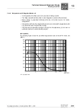
13.1.2 Ambient temperature of DRC
13.1.3 Binary inputs / signal relays
13.1.4 Internal voltage supply 24V_O
DRC type
DRC1
DRC2
Ambient temperature
I
N motor
reduction
Ambient temperature
ϑ
A
– 25 °C to + 60 °C
3 % I
N motor
per K at 40 °C to 60 °C
Binary inputs / signal relays
Input type
DI01 to
DI04
Isolated via optocoupler; PLC-compatible to EN 61131-2
(digital inputs type 1)
R
i
≈
3.0 k
Ω
, I
E
≈
10 mA, sampling cycle
≤
5 ms
Number of inputs
4
Signal level
+15 to +30 V = "1" = Contact closed
–3 to +5 V = "0" = Contact open
Signal relays
Contact data
K1a
Response time
≤
15 ms
DC 24 V / 50 mA / DC 12 to IEC 60947-5-1
(only SELV or PELV circuits)
K1b
Signaling function
NO contact for ready signal
Contact closed:
– with voltage present (24 V system)
– if no fault was detected
– after completion of self-testing phase (when
unit is turned on)
Internal voltage supply for non-safety-related enable signal via STO input
Voltage supply
+24V_O
DC 24 V to EN 61131-2, interference voltage proof and short-circuit proof
0V24_O
Permitted total current
60 mA
Required current for STO-IN
supply
30 mA
P
i
f
kVA
Hz
n

