Operating Instructions – Electronic Motor DRC.-..-DAC
207
13
Technical data
Technical Data and Dimension Sheets
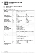
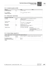
13.1.6 Technical data of AS-Interface
AS-Interface
GLK30A binary
slave
AS-Interface
GLK31A double
slave
AS-Interface
AS-Interface electron-
ics supply
Tl. AS +
Tl. AS -
29.5 V – 31.6 V
(AS-Interface power supply to EN 50295)
I
E
only AS-Interface:
≤
50 mA
1)
1) The current increases by the demand of the connected sensors (max. sensor current 75 mA).
Control input
Tl. AS +
Tl. AS -
Connection of the AS-interface data line
Connection of the AS-interface data line
Sensor connection
Tl. DI2
Tl. DI3
Tl. V024
Tl. V0
⬜
External sensor input
External sensor input
24 V for sensor supply
Reference potential for sensor supply
Sensor inputs
PLC-compatible in accordance with EN 61131-2
R
i
about 3.0 k
Ω
I
E
about 10 mA
Signal level
+15 V to +30 V
–3 V to +5 V
"1"
"0"
Maximum sensor cable
length
15 m
AS-Interface GLK30A
Protocol variant
AS-Interface binary slave with a S-7.F profile "four bit I/O mode slave"
AS-Interface profile
S-7.F
I/O configuration
7
hex
ID code
F
hex
ext. ID code 2
E
hex
ext. ID code1
F
hex
Address
1 to 31 (factory setting: 0), can be changed as often as required
AS-Interface GLK31A
Slave A
Slave B
Protocol variant
AS-Interface double slave in extended address mode
AS-Interface specification V3.0, rev.02 in conjunction with M4 master profile
AS-Interface profile
S-7.A.7.7
S-7.A.5.F
I/O configuration
7
hex
7
hex
ID code
A
hex
A
hex
ext. ID code 2
7
hex
5
hex
ext. ID code1
7
hex
7
hex
Function
4DI/4DO cyclical
4PDI/3PDO
Serial acyclic
Address
1 to 31 (factory setting: 0), can be changed as often as required
P
i
f
kVA
Hz
n

