22
Operating Instructions – Electronic Motor DRC.-..-DAC
4
Installation notes
Mechanical Installation
4
Mechanical Installation
4.1
Installation notes
4.2
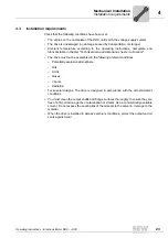
Required tools and resources
• Set of wrenches
• Torque wrench
• Mounting device
• Compensation elements (shims and spacing rings), if necessary
• Mounting materials for output components
• Lubricant (e.g. NOCO
®
Fluid)
• Standard parts are not included in the delivery
4.2.1
Installation tolerances for shaft ends
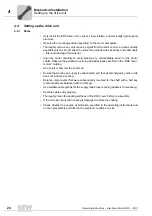
The following table shows the permitted tolerances of shaft ends and flanges of the
DRC motor.
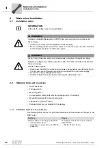
INFORMATION
Adhere to the safety notes during installation.
WARNING
Improper installation/disassembly of DRC drive units and mount-on components.
Risk of injury.
• Adhere to the notes about installation and disassembly.
• Before releasing shaft connections, make sure that there are no active torsional
moments present (tensions within the system).
WARNING
Risk of injury if the drive starts up unintentionally and danger of electrical voltage.
Dangerous voltages may still be present for up to 10 minutes after disconnection from
the power supply.
Severe or fatal injuries.
• Disconnect the DRC drive unit from the power supply before you start working on
the unit and secure it against unintentional reconnection to the power supply.
• Secure the output shaft against rotation.
• Wait for at least 10 minutes before removing the electronics cover.
Shaft end
Flanges
Diameter tolerance according to EN 50347
•
ISO j6 with Ø
≤
26 mm
•
Center bore in accordance with DIN 332,
shape DR..
Centering shoulder tolerance in accordance
with EN 50347
•
ISO j6 with Ø
≤
250 mm


