Operating Instructions – Electronic Motor DRC.-..-DAC
39
5
Installation instructions
Electrical Installation
5.2.2
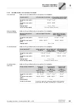
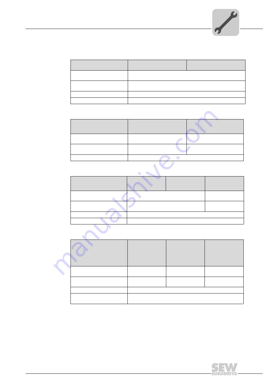
Permitted cable cross section of terminals
Line terminals
Adhere to the permitted cable cross sections for installation:
External braking
resistor terminals
Adhere to the permitted cable cross sections for installation:
Control terminals
Adhere to the permitted cable cross sections for installation:
Communication
terminals
Adhere to the permitted cable cross sections for installation:
Line terminals X2
without conductor end sleeve
with conductor end sleeve (with
or without insulating shroud)
Connection cross section
(mm
2
)
0.5 mm
2
– 6 mm
2
Connection cross section
(AWG)
AWG20 – AWG10
Stripping length
13 mm – 15 mm
Current carrying capacity
24 A (max. continuous current)
External braking resistor
terminals X5
without conductor end sleeve
with conductor end sleeve
(with or without insulating
shroud)
Connection cross section
(mm
2
)
0.08 mm
2
– 4.0 mm
2
0.25 mm
2
– 2.5 mm
2
Connection cross section
(AWG)
AWG28 – AWG12
AWG 23 – AWG 14
Stripping length
8 mm – 9 mm
Control terminals X7
without conductor
end sleeve
with conductor end
sleeve (without
insulating shroud)
with conductor end
sleeve (with insulat-
ing shroud)
Connection cross section
(mm
2
)
0.08 mm
2
– 2.5 mm
2
0.25 mm
2
– 1.5 mm
2
Connection cross section
(AWG)
AWG 28 – AWG 14
AWG 23 – AWG 16
Stripping length
5 mm – 6 mm
Current carrying capacity
3.5 A max. continuous current
Communication terminals X1
Single-wire
conductor
(bare wire)
Conductor with
conductor end
sleeve
without insulating
shroud
Conductor with
conductor end
sleeve
with insulating
shroud
Flexible conductor
(bare litz wire)
Connection cross section
(mm
2
)
0.5 – 1.5 mm
2
0.5 mm
2
– 1.0 mm
2
0.5 mm
2
Connection cross section
(AWG)
AWG20 – AWG16
AWG20 – AWG17
AWG20
Stripping length
9 mm
Conductor end sleeves
Connect only single-wire conductors or flexible conductors with or
without conductor end sleeve (DIN 46228 part 1, material E-CU)


