46
Operating Instructions – Electronic Motor DRC.-..-DAC
5
Terminal assignment
Electrical Installation
5.3
Terminal assignment
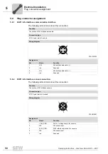
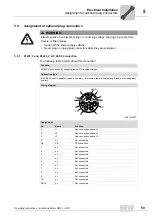
The following figure shows the terminal assignment of DRC-DAC:
WARNING
Electric shock due to regenerative operation when the shaft turns.
Severe or fatal injuries.
• Secure the output shaft against rotation when the electronics cover is removed.
4727525899
Assignment
Terminal
No.
Name
Marking
Function (permitted tightening torque)
X2 line
terminals
1
L1
Brown
Line connection phase L1 – IN
2
L2
Black
Line connection phase L2 – IN
3
L3
Gray
Line connection phase L3 – IN
11
L1
Brown
Line connection phase L1 – OUT
12
L2
Black
Line connection phase L2 – OUT
13
L3
Gray
Line connection phase L3 – OUT
–
PE
–
Protective earth connection (2.0 to 3.3 Nm )
X5 braking
resistor
terminals
1
BW
–
Braking resistor connection
2
BW
–
Braking resistor connection
PE
PE
PE
PE
1
2
3
11
12
13
1
2
Braking resistor
terminals
Line terminals
X5
X2
X1
1
2
3
4
5
11 12 13 14 15
21 22 23 24 25
Control terminals
X7
1
2
3
4
5
11 12 13 14 15
21 22 23 24 25
AS+
AS−
DI2
DI3
V024
V024
V0
V0
Communication
terminals

