62
Operating Instructions – Electronic Motor DRC.-..-DAC
5
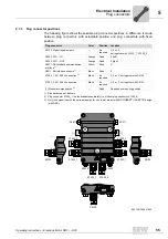
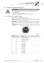
Assignment of optional plug connectors
Electrical Installation
5.9.2
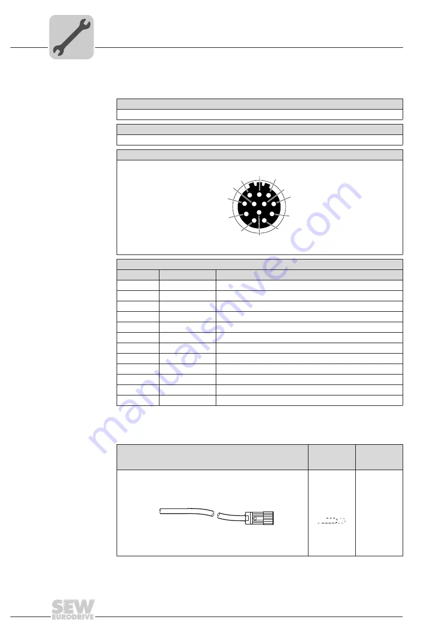
X5132: Digital inputs/outputs
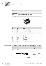
The following table informs about this connection:
Connection cables
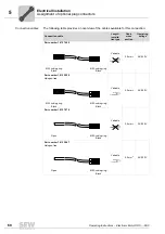
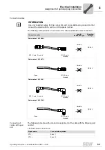
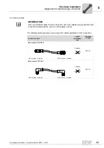
The following table provides an overview of the cables available for this connection:
Function
Digital inputs/outputs for: DRC
Connection type
M23, P insert 12-pole, SpeedTec-capable, Intercontec, female, 0°-coded
Wiring diagram
2264820107
Assignment
No.
Name
Function
1
DI01
Binary input DI01 (CW/stop)
2
DI02
Binary input DI02 (CCW/stop)
3
DI03
Binary input DI03 (setpoint f1/f2)
4
DI04
Binary input DI04 (changeover automatic/local mode)
5
n.c.
Not connected
6
K1a
Signal relay K1a
7
K1b
Signal relay K1b
8
+24V_O
DC 24 V output
9
0V24_O
0V24 reference potential
10
n.c.
Not connected
11
n.c.
Not connected
12
FE
Equipotential bonding/functional ground
9
1
2
7
6
5
11
12
3
4
8
10
Connection cable
Length/
Installation
type
Operating
voltage
Part number 1 174 145 7
Variable
DC 60 V
Open
M23, 12-pole,
0°-coded

