Operating Instructions – Electronic Motor DRC.-..-DAC
79
6
Startup with binary slave GLK30A in "Easy mode"
Startup
6.6.5
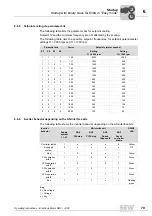
Setpoint scaling via parameter bits
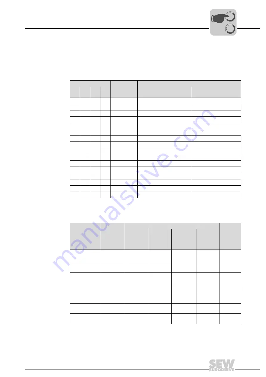
The following table lists the parameter bits for setpoint scaling.
Setpoint f2 and the minimum frequency are not affected by the scaling.
The following table lists the possible setpoint frequencies for setpoint potentiometer
settings f1 = 2000 rpm and f1 = 1000 rpm:
6.6.6
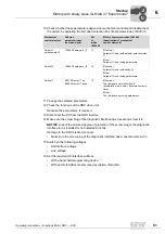
Inverter behavior depending on the AS-Interface bits
The following table shows the inverter behavior depending on the AS-Interface bits:
Parameter bits
Factor
Setpoints (motor speeds)
P3
P2
P1
P0
Setting
f1 = 2000 rpm
Setting
f1 = 1000 rpm
1
1
1
1
1.00
2000
1000
1
1
1
0
1.11
1800
900
1
1
0
1
1.25
1600
800
1
1
0
0
1.43
1400
700
1
0
1
1
1.67
1200
600
1
0
1
0
2.00
1000
500
1
0
0
1
2.22
900
450
1
0
0
0
2.50
800
400
0
1
1
1
2.86
700
350
0
1
1
0
3.33
600
300
0
1
0
1
4.00
500
250
0
1
0
0
5.00
400
200
0
0
1
1
6.67
300
150
0
0
1
0
10.00
200
100
0
0
0
1
14.30
140
70
0
0
0
0
20.00
100
50
Inverter
behavior
AS-Interface bit
DRIVE
LED
Supply
system
L1-L3
DO0
DO1
DO2
DO3
CW/stop
CCW/stop
Speed
f2/speed f1
Reset/
controller
enable
Controller inhibit
1
x
x
x
0
Yellow
No supply
system
0
x
x
x
x
Off
Stop
1
0
0
x
1
Yellow
CW operation
with f1
1
1
0
0
1
Green
CCW operation
with f1
1
0
1
0
1
Green
CW operation
with f2
1
1
0
1
1
Green
CCW operation
with f2
1
0
1
1
1
Green
Stop
1
1
1
x
1
Flashing
green
Key
0 = No voltage
1 = Voltage
x = Any
00
I

