102
Operating Instructions – MOVIDRIVE® MDR60A/61B
11
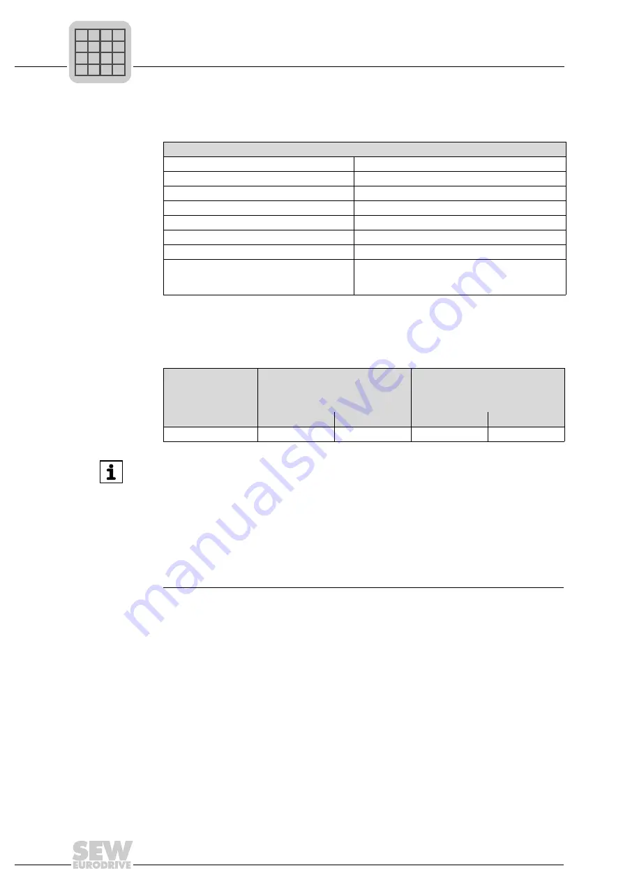
Rated data
Technical Data (MDR60A1320-503-00)
11.3 Rated data
11.4 Current carrying capacity
MOVIDRIVE
®
MDR60A1320-503-00
Nominal range of the linked supply voltage U
N
380 V
≤
U
N
≤
500 V
Tolerance of the linked supply voltage U
N
342 V
≤
U
N
≤
550 V
Mains frequency f
N
40 Hz ... 60 Hz ±10 %
Overload capacity
→
Chapter "Current carrying capacity"
Efficiency
η
Approximately 98 % (2 % thermal losses)
Power factor G
≈
0.7 - 0.95
Cooling air consumption
700 m
3
/h
Power reduction
ϑ
U
40 °C ... 55 °C
→
3 %/K
1000 m above sea level < h
≤
4000 m above sea level
→
5 %/1000 m
Unit type
Driving operation
Braking operation
Free-wheeling diode
IGBT modules
I
eff Phase
I
eff Phase
100 %
1 min in 10 min
100 %
1 min in 10 min
MDR60A 1320-503-00
260 A
360 A
260 A
330 A
INFORMATION
• Just like the input of a drive controller, the incoming side of the MOVIDRIVE
®
MDR60A1320-503-00 is not overload protected. Make sure during dimensioning
that the maximum DC input current of the driver controller (including overload fac-
tor) does not exceed the input current of the regenerative power supply unit. If that
should still be the case, the programmable motor current limit of the drive controller
should be identical to that of the regenerative power supply unit. You will have to
take the overload factor of the drive controller into consideration in this instance as
well.
• Keep in mind when determining the regenerative power that the actual current re-
generative power always depends on the actually existing supply voltage.
P
i
f
kVA
Hz
n

