110
Operating Instructions – MOVIDRIVE® MDR60A/61B
12
Electrical connection
Installation (MDR60A1320-503-00)
12.3.2 Control cables
• Connect the control cables to the control terminal strip X2 (
→
section "Terminal as-
signment control terminal strip X2").
• Do not route the control cables parallel to the problem-prone motor cables.
• Apply the shielding of the control cables over a wide area of the metal cable glands
on the flange.
12.3.3 Control connections
The control terminal strip X2 is located at the bottom of the device. The terminal block
is modular and can be easily wired.
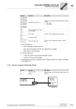
Use the terminal control strip X2 to connect via relay certain messages such as ready
for operation or a group fault outside the unit. You can also perform an external RESET
or switching function via the control terminal strip X2 and link it with the frequency in-
verter.
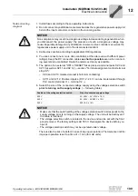
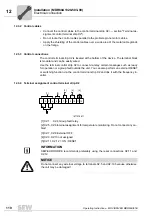
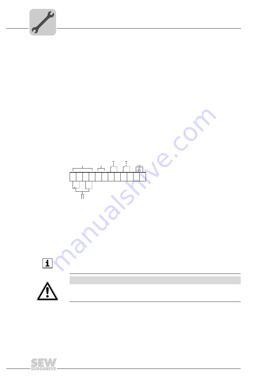
12.3.4 Terminal assignment control terminal strip X2
1877276811
[1] X2:1 ... X2:4 Group fault relay
[2] X2:5, X2:6 Internal assignment for temperature monitoring. Do not connect any ca-
bles!
[3] X2:7, X2:8 External OFF
[4] X2:9, X2:10 not assigned
[5] X2:11, X2:12 = ON / RESET
12
11
10
9
8
7
6
5
4
3
2
1
+ -
[1]
[2]
[3]
[4]
[5]
INFORMATION
SEW-EURODRIVE recommends preferably using the reset connections X2:11 and
X2:12.
NOTICE
Do not connect any external voltage to terminals X2:5 and X2:10 because otherwise
the unit may be damaged!

