118
Operating Instructions – MOVIDRIVE® MDR60A/61B
14
Important notes on configuration
Configuration (MDR60A1320-503-00)
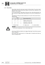
14.1.5 Phase failure
Phase fault monitoring monitors power supply of all three phases. The unit will remain
fully functional as far as internal power supply is concerned even with failure of one
phase (e.g. error memory).
The unit can respond to a phase failure in two ways. One is "two-phase operation", the
other is that the unit stops operation and indicates the error via the centralized alarm re-
lay.
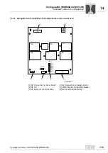
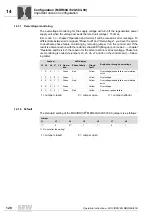
Phase failure monitoring is coded via jumpers J3, J5, J6 and J7 to the control board (
→
following table).
Error memory "ON" means that the error display "Phase failure" via LED remains active
until it is confirmed.
Error memory "OFF" means that the error "Phase failure" is indicated via the LED only
while it is actually present.
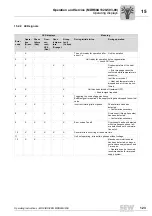
Jumper
Phase failure monitoring
J3
J5
J6
J7
1
0
0
1
Sensitive, error memory "ON"
1
1
1
1
insensitive, error memory "ON"
0
X
X
1
Deactivated, error memory "ON"
0
X
X
0
Deactivated, error memory "OFF"
1 = Jumper closed
0 = Jumper open
X = Jumper optional
NOTICE
• Remove and install jumper J3 in de-energized state only!

