120
Operating Instructions – MOVIDRIVE® MDR60A/61B
14
Important notes on configuration
Configuration (MDR60A1320-503-00)
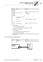
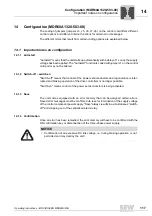
14.1.7 Overvoltage monitoring
The overvoltage monitoring for the supply voltage will turn off the regenerative power
supply unit when the voltage exceeds the rated unit voltage 1.15 times.
Error code 3 (
→
chapter "Operation and Service") will be issued as error message. To
differentiate between error signals "Phase fault" and "Overvoltage", you have the option
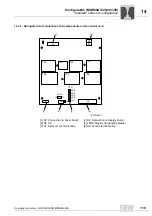
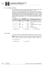
to deactivate phase failure monitoring by removing jumper 3 on the control card. If the
result is a disconnection with the red and yellow LED lighting up (error code 3,
→
chapter
"Operation and Service", the reason for the disconnection is an overvoltage. Phase fail-
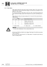
ure monitoring is coded via jumpers J3, J5, J6, J7 and J8 on the control card (
→
follow-
ing table).
14.1.8 Default
The standard setting of the MOVIDRIVE
®
MDR60A1320-503-00 jumpers is as follows:
Jumper
LED display
Evaluation through overvoltage
J3 J5 J6 J7 J8 Opera-
tion
Phase failure
Group
fault
1
X
X
1
1
Green
Red
Yellow
Overvoltage/phase failure commutation
notch
1
X
X
0
1
Green
-
Yellow
Overvoltage
0
X
X
1
1
Green
Red
Yellow
Overvoltage/phase failure commutation
notch
0
X
X
0
1
Green
-
Yellow
Overvoltage
0
X
X
0
1
Green
Red
Yellow
Permanent phase failure
1 = Jumper closed
0 = Jumper open
X = Jumper optional
Jumper
J1
J3
J4
J5
J6
J7
J8
1
1)
1) Do not alter the setting!
0
0
1)
1
1
0
1
1 = Jumper closed
0 = Jumper open

