Operating Instructions – MOVIDRIVE® MDR60A/61B
23
4
Installation notes
Installation (MDR60A0150/0370/0750 and MDR61B1600/2500)
4.1.7
Permitted mounting the braking resistors
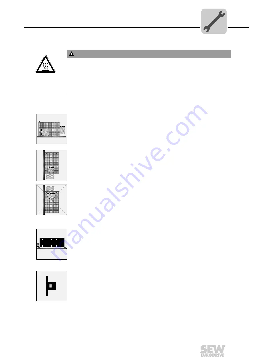
Grid resistors
You must fulfill the following requirements for mounting the grid resistors:
•
Permitted
: Mounting on horizontal surfaces.
•
Permitted
: Mounting on vertical surfaces with terminals pointing downwards when
there is a perforated sheet at the top.
•
Not permitted
: Mounting on vertical surfaces with terminals pointing upwards, to the
right or left. (The connection terminals can be placed within the steel grid, where ap-
propriate. Ensure the proper position of connection terminals also in this case).
Wire resistors
You must fulfill the following requirements for mounting the wire resistors:
•
Permitted
: Mounting on horizontal surfaces.
•
Permitted
: Mounting on vertical surfaces when there is a perforated sheet at the top
or connection terminals at the bottom
WARNING
Non-permissible installation might lead to an accumulation of heat in the braking re-
sistor due to reduced convection. A tripping temperature contact or an overheated
braking resistor can lead to a system standstill.
Adhere to the following minimum distances:
• About 200 mm to adjacent components and walls
• About 300 mm to above components/ceilings


