46
Operating Instructions – MOVIDRIVE® MDR60A/61B
4
Optional scope of delivery for size 7
Installation (MDR60A0150/0370/0750 and MDR61B1600/2500)
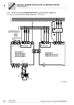
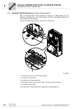
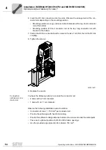
Proceed as follows to connect the mounting base to the MOVIDRIVE
®
B MDR61B size
7:
1. Loosen (not unscrew!) the 4 retaining screws of the front cover [1] until you can lift it
off. Remove the front cover [1].
2. Remove the 2 front covers of the mounting base.
3. The following steps apply to each of the 4 mounting holes.
• Place the lock washer [3] and the washer [4] onto the hex head screw [2] M10×30.
• Plug the pre-mounted hex head screw into the mounting bore and tighten it.
• Apply thread locking compound.
4. Screw the PE strap to the PE busbar with the pre-mounted M10×35 screw.
5. Reinstall the 2 front covers of the mounting base.
6. Install the front cover [1] onto the unit and fasten it using the 4 retaining screws.
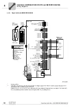
DLS31B mounting
base wiring dia-
gram
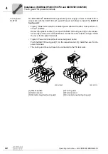
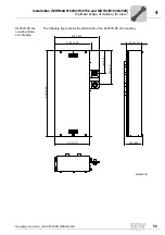
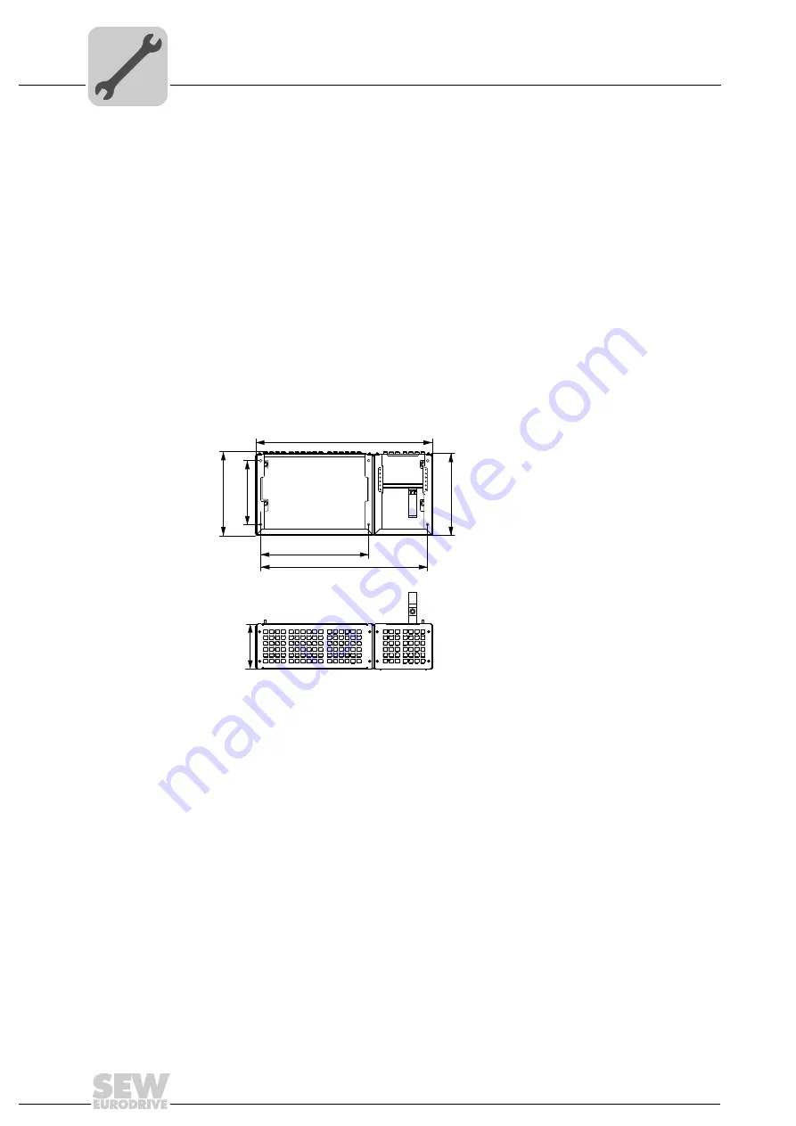
The following figure shows the dimensions of the DLS31B mounting base.
3348431627
899
325
426.69
417
850
550
230

