54
Operating Instructions – MOVIDRIVE® MDR60A/61B
4
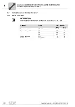
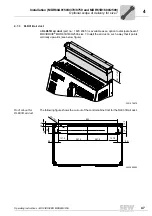
Optional scope of delivery for size 7
Installation (MDR60A0150/0370/0750 and MDR61B1600/2500)
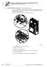
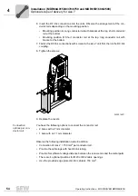
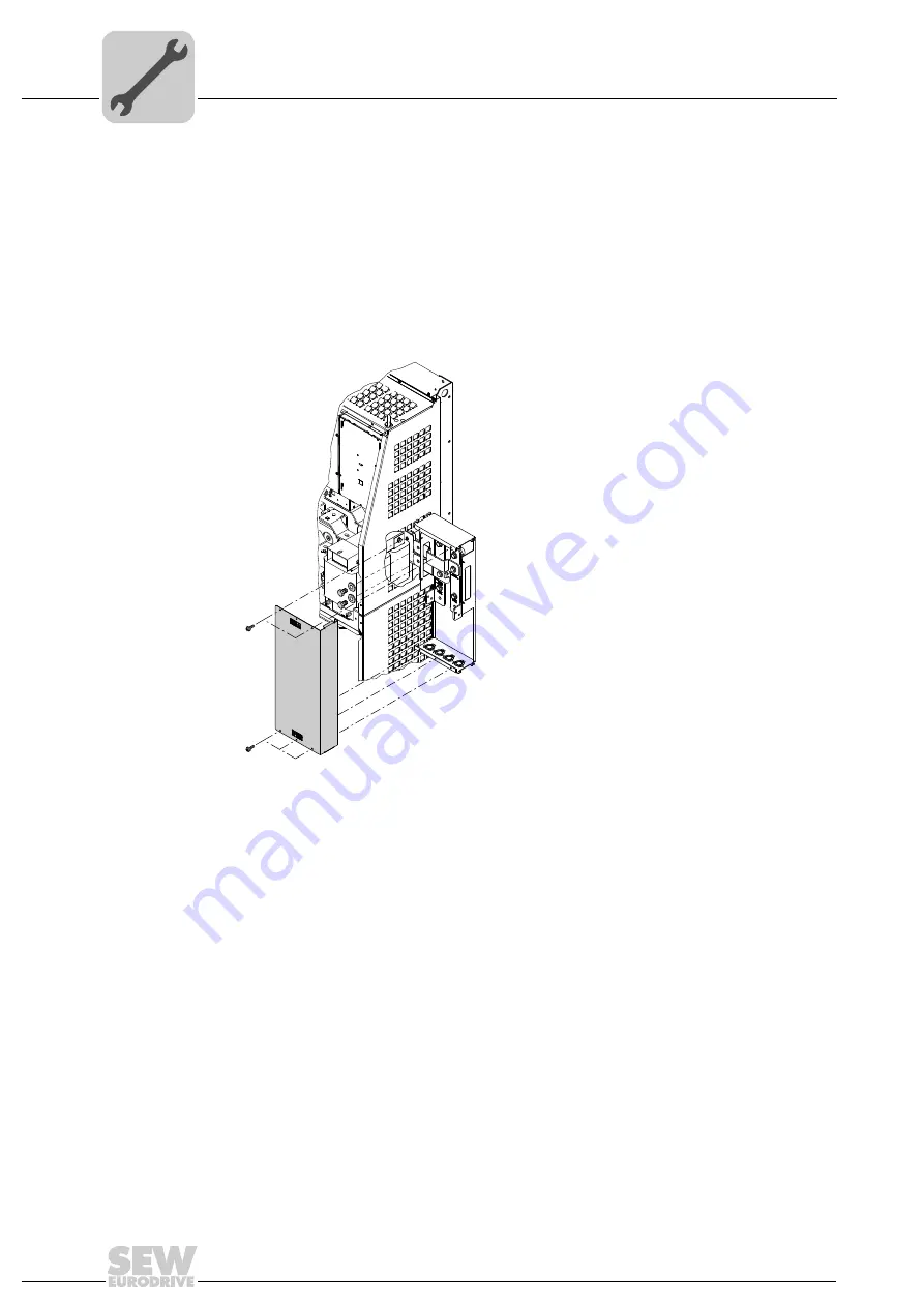
6. Insert the DC link connections into the units. Observe the arrangement of the con-
ductor rails depending on the mounting position.
• Mounting position A: Long conductor rail with bracket at the top, short conductor
rail at the bottom
• Mounting position B: Short conductor rail at the top, long conductor rail with
bracket at the bottom
7. Fasten the DC link connections with screws in the size 7 unit first, then in the DC link
coupling.
8. Tighten the screws.
9. Replace the covers.
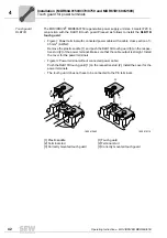
Connection
options per con-
ductor rail
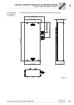
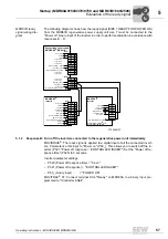
You have the following options to connect the conductor rail:
• 2 bores with a 7 mm diameter
• 1 bore with an 11 mm diameter
Observe the following installation notes in addition:
• Connection of max 2 × 150 mm
2
per conductor rail
• Provide the cable lugs with heat shrink tubing
• Provide for sufficient voltage distance between the screw ends and the metal parts
• There are 4 optional positions for M20 or M32 cable openings
• Use the provided edge protection for cables
≥
150 mm
2
.
3435512971

