Operating Instructions – MOVIDRIVE® MDR60A/61B
57
5
Evaluation of the ready signal
Startup (MDR60A0150/0370/0750 and MDR61B1600/2500)
MDR61B ready
signal wiring dia-
gram
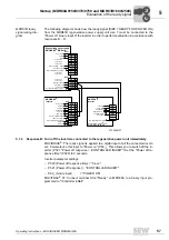
The following diagram shows how the ready signal (SIZE 7 READY FOR POWER ON)
from the MDR61B regenerative power supply unit size 7 must be connected to the
"Power on" binary input of the inverter in order to perform evaluation in accordance with
responses B... D.
5.1.2
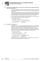
Response B: Turn off the inverters connected to the regenerative power unit immediately
MOVIDRIVE
®
: The ready signal is applied to a digital input of all the connected invert-
ers. Parameterize this input to "Power on" (P60_). This allows you to switch off the in-
verter (P521 "Power off response = /CONTROLLER INHIBIT") Set the "Power off re-
sponse time" (P520) to 0 seconds.
Inverter parameter settings:
– P520 (Power off response time) = "0 sec."
– P521 (Power off response) = "/CONTROLLER INHIBIT"
– P60_ (binary input) = "POWER ON"
MOVITRAC
®
07: Connect terminal X3:4 "Ready" on MDR60A to a binary input pro-
grammed to "/Controller inhibit".
3735668107
X13:
*
DIØØ
DIØ1
DIØ2
DIØ3
DIØ4
DIØ5
DCOM
VO24
DGND
ST11
ST12
DIØ1
DIØ2
DIØ3
DIØ4
DIØ5
DGND
1
2
3
4
5
6
7
8
9
10
11
Ref. potential binary signals
Ref. potential binary signals
Enable/stop
Enable/stop or
/controller inhibit
/Contr. inhibt
CW/stop
CW/stop
CCW/stop
CCW/stop
Ref. X13:DIØØ...DIØ5
DC+24 V output
Error reset
RS-485 -
RS-485+
MOVIDRIVE
inverter
®
Regenerative power supply
MOVIDRIVE MDR61B
®
MOVITRAC
inverter
®
Power on
....
....
*X10 for MOVITRAC
®
07 A
X12 for MOVITRAC
®
B
Error reset
Enable/stop
X16:
DI 6
DI 7
DOØ3
DOØ4
DOØ5
DGND
Ø
Ø
1
2
3
4
5
6
X13:
DIØØ
DIØ1
DIØ2
DIØ3
DIØ4
DIØ5
DCOM*
*
VO2
4
DGND
ST11
ST12
1
2
3
4
5
6
7
8
9
10
11
Ref. potential binary signals
Ref. potential binary signals
/Contr. inhibit
BG7 pwr. ready
precharge ok
no function
Enable
Reset
Ref. X13:DI ØØ ...DI Ø5
DC+24 V output
no function
no function
no function
no function
no function
no function
no function
0
0
I


