58
Operating Instructions – MOVIDRIVE® MDR60A/61B
5
Evaluation of the ready signal
Startup (MDR60A0150/0370/0750 and MDR61B1600/2500)
5.1.3
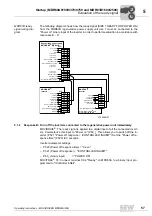
Response C: Turn off the inverters connected to the regenerative power supply unit after delay
time (not for MOVITRAC
®
07):
The following possibility is available if supply system failures during motor operation
should not immediately give rise to an inverter switch-off, e.g. if the power supply system
quality is poor:
Proceed as described for response B. Set the "Power off response time" (P520) to
≥
300
ms so that the ON delay (200 ms) of the regenerative power supply unit is bypassed
once supply voltage has returned. Supply system failures that do not last longer than the
power off response time minus 200 ms do not cause the inverters to disconnect.
If power supply failures should not cause inverters to disconnect in regenerative opera-
tion, the inverters must be equipped with braking resistors.
Inverter parameter settings:
– P520 (Power off response time) = "0.3 ... 5.0 sec."
– P521 (Power off response) = "/CONTROLLER INHIBIT"
– P60_ (binary input) = "POWER ON"
5.1.4
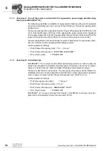
Response D: Controlled stop
MOVIDRIVE
®
: The inverters must be fitted with braking resistors in order to allow the
drives to be brought to a controlled stop (emergency stop ramp) in the event of a power
failure or a fault in the unit. Observe chapter "Braking resistor selection" (page ).
Proceed as described for response B. The emergency stop ramp must be initiated im-
mediately and set as short as possible so that the drive is still in regenerative operation
when it comes to a stop. Set the "Power off response time" (P520) to 0 sec
Inverter parameter settings:
– P137 (emergency stop ramp) = "xxx sec."
– P520 (Power off response time) = "0 sec."
– P521 (Power off response) = "EMERGENCY STOP"
– P60_ (binary input) = "POWER ON"
MOVITRAC
®
07: Connect terminal X3:4 "Ready" on MDR60A to a binary input pro-
grammed to "Enable/stop" and set the stop ramp (P136).
0
0
I

