Operating Instructions – MOVIDRIVE® MDR60A/61B
75
6
Explanation of the parameters
MDR61B1600/2500 – Parameters
group address can be addressed via this address using a multicast telegram. The data
received via group address are not acknowledged by MOVIDRIVE
®
B. Group address
100 means that no group is assigned to the inverter.
P812 RS485 time-
out interval
Setting range: 0 – 650 s
P812
sets the monitoring time for data transmission via the serial interface.
MOVIDRIVE
®
B performs the error response set in if there is no cyclical process data
exchange via the serial interface for the period set in parameter 812. Serial data trans-
mission is not monitored when
P812
is set to 0. Monitoring is activated with the first cy-
clical data exchange.
P83x Fault
responses
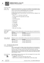
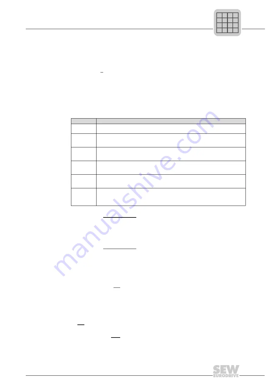
The following responses can be programmed:
P833 Response to
RS485 TIMEOUT
Factory setting: DISPLAY ONLY
P833
programs the error response that is triggered by the RS485 timeout monitoring.
The response time of the monitoring process can be set with
P836 Response
SBus TIMEOUT 1
Factory setting: DISPLAY ONLY
P836
programs the error response that is triggered by system bus timeout monitoring.
The response time of the monitoring process can be set with
.
P84x Reset behavior
P840 Manual reset
Setting range: YES / NO
• YES: The error in the regenerative power supply unit is reset. In case of an error, you
can press the [
←
/ Del] key on the DBG60B to access
P840
directly.
P840
is also
available in the "Parameters" main menu in SHELL.
P840
automatically reverts to
NO after the reset. Activating the manual reset does not have any effect if there is no
error present.
• NO: No reset.
P841 Auto reset
Setting range: ON / OFF
• ON: The auto reset function is activated. In case of an error, this function automati-
cally resets the unit after
. A maximum of five auto resets is possi-
Response
Description
NO
RESPONSE
Neither an error is displayed nor an error response is performed. The signaled error is
ignored.
DISPLAY
ONLY
The error is displayed (in 7-segment display and SHELL), the fault output is set (if pro-
grammed). The unit performs no other error responses. The error can be reset (terminal,
RS485, fieldbus, auto-reset).
OUTPUT
STAGE
INHIBIT
The inverter switches off immediately and an error is signaled. The line inverter is inhibited.
The ready signal is revoked and the error output is set, if programmed. Restart is only possi-
ble after the error has been reset. The line contactor remains on.
DE-ENER-
GIZE LINE
CONTACTOR
The inverter switches off immediately and an error is signaled. The output stage is inhibited.
The error is signaled via the terminal, if programmed. The line contactor opens.
DISPLAY
ONLY WITH
AUTO-RESET
A re-established fieldbus connection resets the display.
INHIBIT OUT-
PUT STAGE
WITH AUTO-
RESET
A re-established fieldbus connection enables the line inverter.
P
i
f
kVA
Hz
n

