98
Operating Instructions – MOVIDRIVE® MDR60A/61B
10
General information
Safety Notes (MDR60A1320-503-00)
10.1.5 Cable and transfer resistors
The data on current carrying capacity of cables usually refers to copper conductors. Use
larger cross sections for aluminum conductors due to the higher specific resistance.
For both kinds of conductor material you will have to ensure that the connection points
of the conductors are low-resistance and that their number is kept as low as possible.
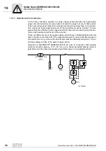
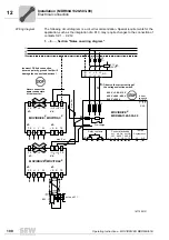
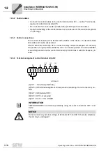
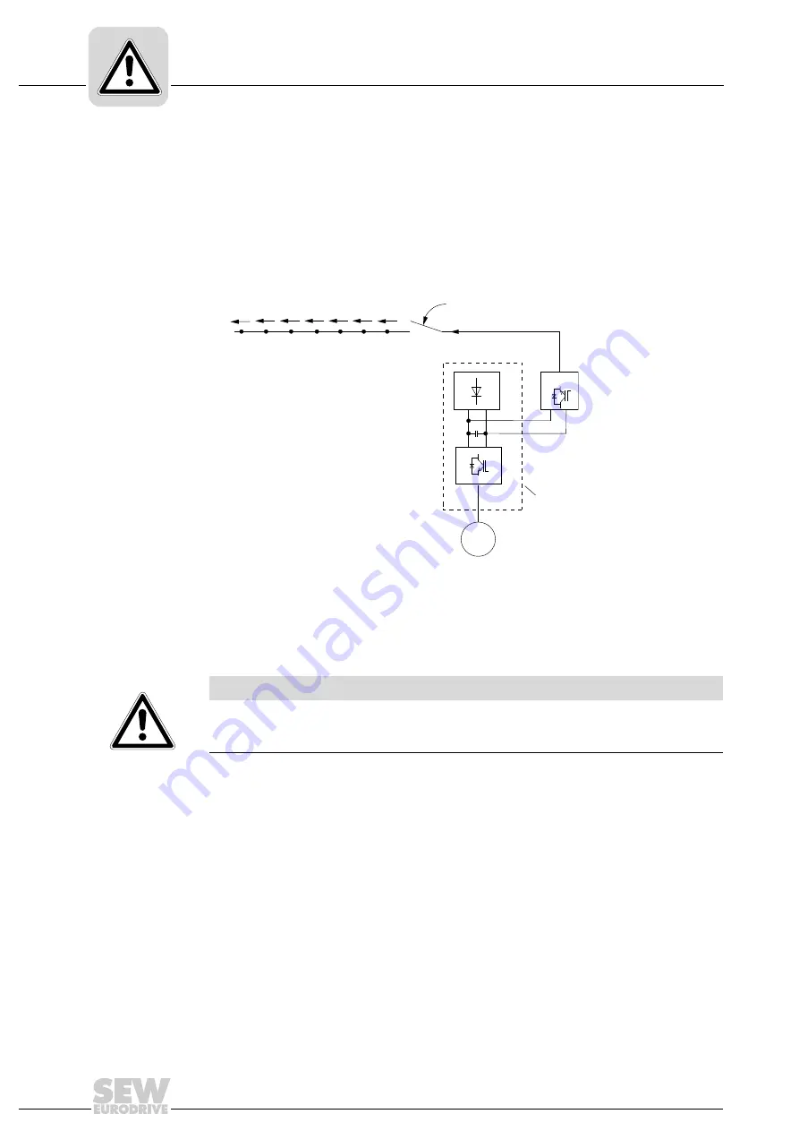
As shown in the following illustration, too many or too high-resistance terminal connec-
tions (D U) can result in an excessive voltage drop during driving operation and an ex-
cessive voltage peak in regenerative operation.
Based on a stable power supply [1] with 400 V rated voltage and a regenerative current
of 80 A, there will be a voltage loss of 8 V at a poorly designed terminal connection of
100 m
Ω
. A well designed terminal connection has a transfer resistance of ca. 1 m
Ω
.
There will be a voltage of 456 V in regenerative operation at the power switch with 7 ter-
minal connections.
1877091339
M
I
MDR
Δ
U
Δ
U
Δ
U
Δ
U
Δ
U
Δ
U
Δ
U
[1]
[2]
MOVIDRIVE
®
NOTICE
Overvoltages can cause irreparable damage to the connected drive controller
[2] and/or the regenerative power supply unit as well as the other loads.


