Operating Instructions – MOVIDRIVE® MDR60A/61B
103
11
Fuses and cable cross sections
Technical Data (MDR60A1320-503-00)
11.5 Fuses and cable cross sections
The power supply connection of the regenerative power supply unit takes place via ter-
minals L1, L2 and L3 at the commutation choke and PE on the heat sink. Match the input
fuse according to the current carrying capacity of the permitted connection cable. The
listed manufacturers are recommendations only; you can certainly use comparable
types from other manufacturers (e.g. Jean Müller, Ferraz, Bussmann).
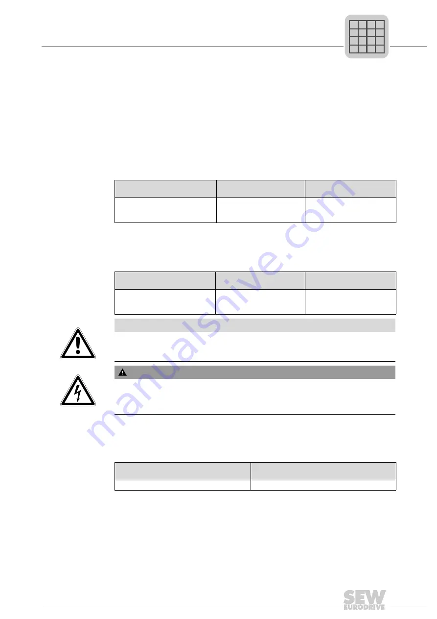
11.5.1 Fuses to connect to incoming cable
You can connect the semiconductor fuses listed in the following table to the incoming
cable of the regenerative power supply unit.
11.5.2 Fuses used in unit
The semiconductor fuses listed in the following table are installed in the regenerative
power supply unit.
11.5.3 Radio interference suppression filter
Install a radio interference suppression filter of category A in the MOVIDRIVE
®
MDR60A
1320-503-00 to meet EMC regulations.
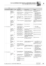
Unit type
Max. fuse
Connection/max. line cross
section of supply cable
MOVIDRIVE
®
MDR60A1320-503-00
Siba 20 713 32.500
AC 500 A / AC 1100 V /
110 mm NH01
Terminal stud M10 / 185 mm
2
Unit type
DC fuses (high-speed semi-
conductor fuses)
Connection/max. line cross
section of supply cable
MOVIDRIVE
®
MDR60A1320-503-00 Siba 20 713 32.630
AC 630 A / AC 1100 V /
110 mm NH01
Terminal stud M10 / 185 mm
2
NOTICE
Contact SEW-EURODRIVE in case the fuses are activated; other protection mea-
sures may have been triggered in the unit. Replace internal fuses with original equip-
ment only.
WARNING
Electric shock from live components.
Severe or fatal injuries.
•
Replace fuses in deenergized state only!
Unit type
Order number for radio interference suppression
filter
MOVIDRIVE
®
MDR60A1320-503-00
NF300-503
P
i
f
kVA
Hz
n

