Operating Instructions – MOVIDRIVE® MDR60A/61B
137
16
Dimension drawings
Technical Data – Basic Unit
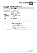
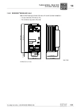
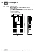
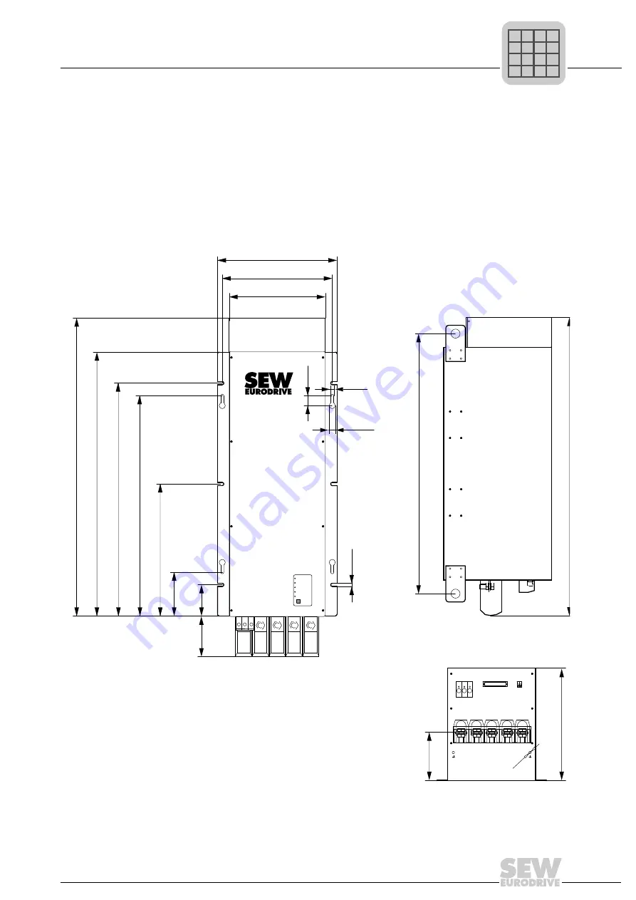
16.8.4 MOVIDRIVE
®
MDR60A1320 size 6
Observe the following minimum clearance for control cabinet installation:
• Above 100 mm (3.9 in)
• Do not install any components that are sensitive to high temperatures within 300 mm
(11.8 in) above the unit, for example contactors or fuses.
• No clearance required below
• 70 mm (2.8 in) on the side
1454342923
All dimensions in mm (in)
1
+
3
2
SKS
-
L1
L2
L3
off/collective error
phase failure
overcurrent/UcE
operation
overtemperature
reset
129
(5.07)
98
(3.85)
138
(5.43)
417 (16.41)
696 (27.40)
736 (28.97)
834 (32.83)
942 (37.08)
304 (11.96)
348 (13.70)
378 (14.88)
10
(0.39)
19.32
(0.76)
31
(1.22)
10
(0.39)
389.5 (15.33)
1070.02 (42.12)
169.5
(6.67)
SKS
+
PE
X2
-
L1
L2
L3
PE
8M
933.5 (36.75)
P
i
f
kVA
Hz
n

