18
Operating Instructions – MOVIDRIVE® MDR60A/61B
3
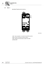
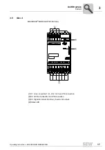
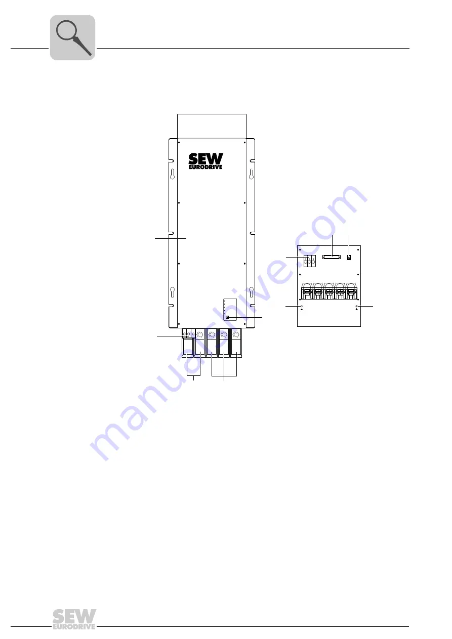
Size 6
Unit Structure
3.6
Size 6
MOVIDRIVE
®
MDR60A1320-503-00
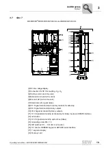
[1] PE connection
[2] line connection 1/L1, 2/L2, 3/L3
[3] Connection for DC link coupling -U
Z
+U
Z
[4] Terminal strip SKS (do not wire!)
[5] Signal terminal strip binary inputs and outputs
[6] Inhibit input A1/A2
[7] Status LED
[8] Voltage selection switch (internal)
1
+
3
2
SKS
-
L1
L2
L3
off/collective error
phase failure
overcurrent/UcE
operation
overtemperature
reset
SKS
+
PE
X2
-
L1
L2
L3
PE
[1]
[1]
[2]
[3]
[4]
[4]
[5]
[6]
[7]
[8]


