Operating Instructions – MOVIDRIVE® MDR60A/61B
21
4
Installation notes
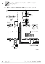
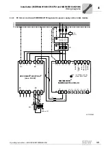
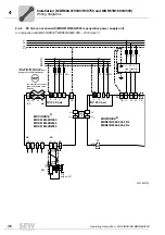
Installation (MDR60A0150/0370/0750 and MDR61B1600/2500)
4
Installation (MDR60A0150/0370/0750 and MDR61B1600/2500)
This chapter illustrates the installation of the following regenerative power supply units:
• MOVIDRIVE
®
MDR60A0150-503-00
• MOVIDRIVE
®
MDR60A0370-503-00
• MOVIDRIVE
®
MDR60A0750-503-00
• MOVIDRIVE
®
MDR61B1600-503-00/L
• MOVIDRIVE
®
MDR61B2500-503-00/L
4.1
Installation notes
•
You must observe the safety notes during installation
•
In order to protect the MDR60A/61B regenerative power supply unit, you have
to evaluate the ready signal (
→
chapter "Startup").
•
For operation with MOVIDRIVE
®
MDR60A/61B, do not connect the power sup-
ply connections of the individual MOVIDRIVE
®
MDX60B/61B inverters to the
power supply! (the MOVIDRIVE
®
MDR60A0150-503-00 installed as a brake
module is excepted)
4.1.1
Tightening torques
• Only use
genuine connection elements
. Observe the
permitted tightening
torques
of the power terminals for MOVIDRIVE
®
inverters.
WARNING
During operation, the heat sink temperature may rise to more than 70 °C.
Risk of burns and fire.
• Choose a suitable installation location.
• Do not touch the heat sink.


