Operating Instructions – MOVIDRIVE® MDR60A/61B
35
4
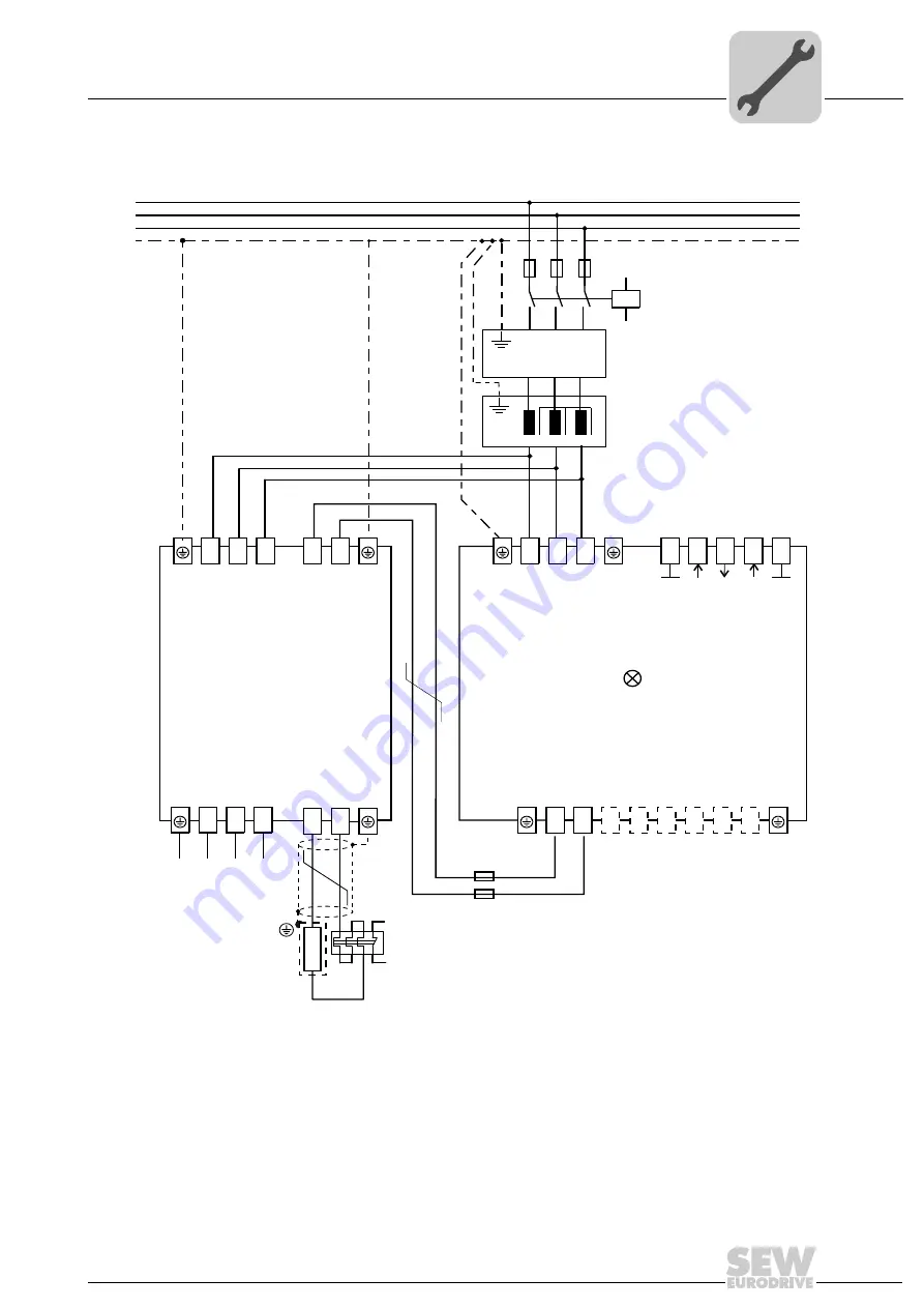
Wiring diagrams
Installation (MDR60A0150/0370/0750 and MDR61B1600/2500)
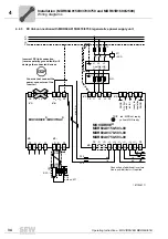
4.4.4
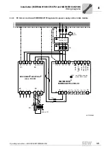
DC link connection with MDR60A0150 regenerative power supply unit as brake module
3627533963
L1
L2
L3
PE
F12
F11
F13
K12
(AC3)
DGND
DGND
8b
7c
8c
1
2
3
®
MOVIDRIVE
MDR60A0150-503-00
7b
7a
11
12
8a
F25
F26
X1:
X2:
3
4
5
X3:
PE
PE L1
L2
L3
bk
rd
PE
PE
MOVIDRIVE / MOVITRAC
(max. 30 kW)
®
4
5
6
8
7
+R
PE
X1:
X4:
X2:
9
8
X3:
PE L1
L2
L3
PE
W
-R
PE
max. 5 m
BW...
l
+U
Z
-U
Z
-D +D
+U
Z
-U
Z
+U
Z
-U
Z
F16
acts on K11
TRIP red: MDR not ready
yellow: MDR ready
output
-U
Z
+U
Z
Ready for
operation
V
U
DC+24 V
-
2
1
inhibit
®
'
U1 V1 W1
U2 V2 W2
ND...
L2'
L1 L2
L3
L1'
L3'
line filter NF...
3
1
2

