48
Operating Instructions – MOVIDRIVE® MDR60A/61B
4
Optional scope of delivery for size 7
Installation (MDR60A0150/0370/0750 and MDR61B1600/2500)
4.7.4
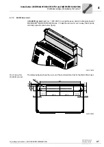
DC link adapter 2Q DLZ12B
The
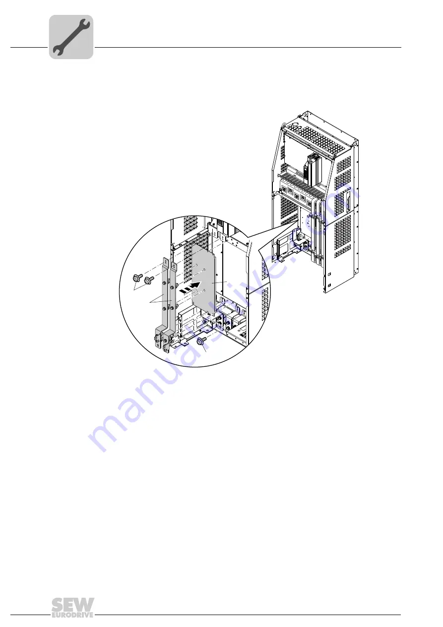
DC link adapter 2Q DLZ12B
(part no.: 1 822 729 5) can be used to provide a DC
link connection at the bottom of the unit:
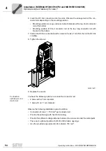
1. Loosen the 4 screws of both the upper and lower cover and remove them.
2. Loosen the 5 screws of the insert and remove it.
3. Place the cover panel on the fastening pin of the slot for the brake chopper module.
4. Position the 2 upper retaining screws [2] of the cover panel [1] in the frame. Position
the 2 lower retaining screws of the cover panel in the frame.
5. Screw the insulating spacers tightly to the cover panel [1].
6. Screw the insulating spacers tightly to the frame (bottom).
7. Position the 2 screws of the fixing strap -U
z
at the DC link (top left).
8. Position the 2 screws of the fixing strap +U
z
at the DC link (top right).
9. Position the 4 screws of the fixing straps -U
z
and +U
z
on the insulating spacer.
10.Tighten all screws of the fixing scraps -U
z
and +U
z
.
11.Replace the covers.
2276336523
[3]
[2] 4x
[4]
[1]

