72
Operating Instructions – MOVIDRIVE® MDR60A/61B
6
Explanation of the parameters
MDR61B1600/2500 – Parameters
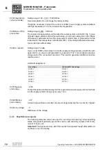
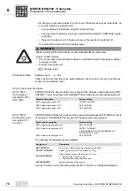
P294 Integral time
current controller
Setting range: 0.00 – 7.50 – 10000.00 ms
Recommendation: Do not change the factory setting.
It might be necessary to adjust the current controller to poor supply system conditions
with high impedance. To do so, increase the integral time.
P295 Mains off tol-
erance time
Setting range: 0.000 – 5.000 ms
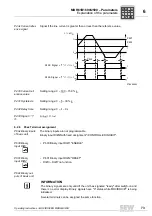
The supply and regenerative unit monitors the supply system and the DC link. In case
of faulty supply systems and brief power failures, you can set a delay time in the "Mains
off tolerance" parameter before the supply system monitor trips. A prerequisite for this
is that the DC link voltage does not fall below 435 V. If the voltage falls below this value,
the monitor trips without delay.
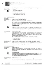
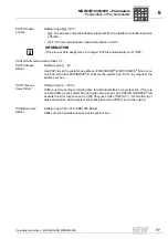
P296 U
z
reduced
Setting range: Yes/No
If you connect SEW units in sizes 0 to 6 to the supply and regenerative unit with line volt-
ages
≥
440 V, you have to set parameter U
z
reduced to "Yes". This avoids an excessive
voltage load of the connected consumers. This function generates additional inductive
reactive power.
Automatic assignment:
P297 Regener-
ated energy
…kWh
Total of the active electrical energy that the regenerative power supply unit has fed back
into the supply system; storage cycle every 1 min.
P298 Effective
power display
…kW
Amount of power that is currently consumed or regenerated by the line inverter. Signed.
P299 Line voltage
…V
RMS value of line voltage
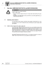
6.2.5
P4xx Reference signals
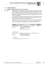
The following reference values are used for recording and reporting certain operating
states. All signals of parameter group P4xx can be read via binary outputs (
).
Important:
The signals are only valid if the inverter has signaled "ready" after switch-on
and there is no error display.
Line voltage
Controlled DC link voltage
AC 380 V
DC 644 V
AC 400 V
DC 670 V
AC 440 V
DC 700 V
AC 460 V
DC 700 V
AC 480 V
DC 700 V
AC 500 V
DC 710 V
P
i
f
kVA
Hz
n

