Operating Instructions – MOVIDRIVE® MDR60A/61B
83
8
Fault information
Service (MDR60A0150/0370/0750 and MDR61B1600/2500)
8
Service (MDR60A0150/0370/0750 and MDR61B1600/2500)
8.1
Fault information
8.1.1
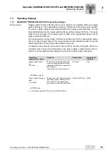
MOVIDRIVE
®
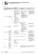
MDR60A0150/0370/0750 error information
Regenerative
power supply reset
After a switch-off the regenerative power supply is reset automatically (
→
chapter "Op-
erating behavior").
Inverter
The power off response does not produce an error message in the inverter (no reset re-
quired). Other errors, such as "U
Z
overvoltage" must be reset. Program a binary input
on the inverter to "RESET" for that purpose. The reset is activated by a positive edge
("0"
→
"1" signal). A reset can also be achieved by switching the supply voltage off and
on again.
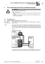
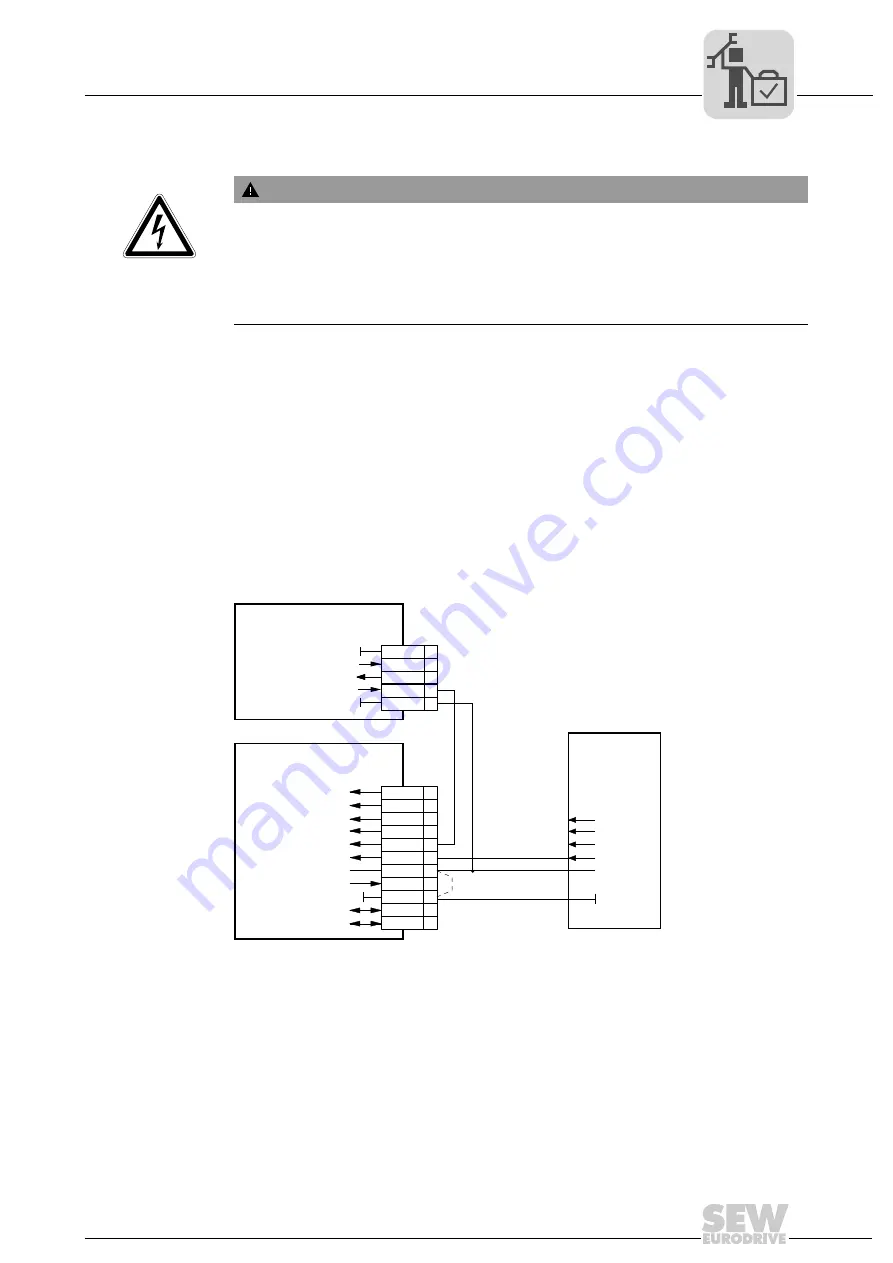
** If the binary inputs are connected to the DC 24 V voltage supply X13:8 "VO24", install
a jumper between X13:7 and X13:9 (DCOM - DGND) on the MOVIDRIVE
®
inverter.
10 minutes
WARNING
Electric shock due to charged capacitors
Severe or fatal injuries.
• Observe a minimum switch-off time of 10 minutes after disconnecting the power
supply.
• Regardless of the LED display, make sure that the unit is deenergized before you
touch any power elements.
1877049483
Higher-level
controller
Binary
outputs
Ref. potential binary signals
Enable/stop
/Contr. inhibit
CW/stop
CCW/stop
Ref. X13:DIØØ...DIØ5
Ref. potential
bin. outptuts
DC+24-V output
Reset
RS-485
-
RS-485+
DGND
+24 V
-
Bereit
DGND
Regenerative power supply
unit MDR60A
MOVIDRIVE
inverter
®
DGND
X13:
DIØØ
DIØ1
DIØ2
DIØ3
DIØ4
DIØ5
DCOM**
VO24
DGND
ST11
ST12
1
2
3
4
5
6
7
8
9
10
11
X3:
1
2
3
4
5
DGND
+24 V
INHBT
RDY
DGND
Power on
Ref. potential binary signals
Ref. potential binary signals
DC+24 V output
Inhibit
Ready signal


