108
Operating Instructions – MOVIAXIS® MX Multi-Axis Servo Inverter
5
CAN2 bus information and settings
Startup
5.3
CAN2 bus information and settings
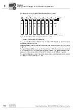
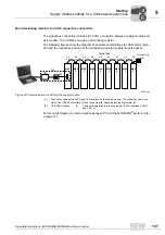
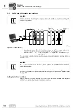
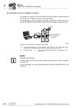
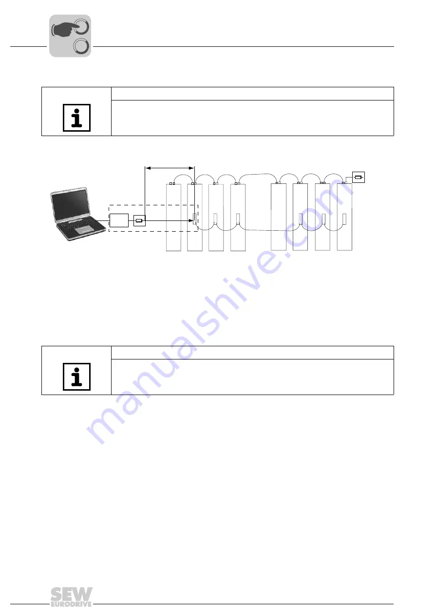
The maximum permitted cable length between terminating resistor and the first axis
module is 5 m.
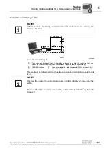
For more information on communication between PC and the MOVIAXIS
®
system, refer
to page 111.
Setting the CAN2 axis address
All axis modules are set to address "4" at the factory. Each axis module must be given
a CAN2 axis address by means of parameter setting.
NOTES
CAN connections should only be implemented in the control cabinet to avoid any dif-
ference of potential.
62478aen
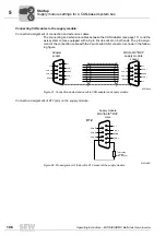
Figure 64: CAN2 cable length
MXP
max. 5 m
MXA
MXA
MXA
X9
a / b
a / b
X9
a / b
MXP
MXA
MXA
MXA
X9
a / b
X9
a / b
X9
a / b
X9
a / b
Terminating
resistor
Signal bus
[2]
[3]
[1]
[1]
Connection cable between PC and CAN interface on the axis module. The connection cable consists
of the USB-CAN interface [2] and the cable with integrated terminating resistor [3].
[2]
USB-CAN interface
[3]
Cable with integrated terminating resistor (120
Ω
between CAN_H
and CAN_L)
NOTES
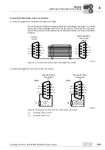
For the connection between the axis systems, please use pre-fabricated cables from
SEW-EURODRIVE.
0
0
I
Summary of Contents for MOVIAXIS MX
Page 2: ...SEW EURODRIVE Driving the world...
Page 210: ......
Page 211: ...SEW EURODRIVE Driving the world...

