Operating Instructions – MOVIAXIS® MX Multi-Axis Servo Inverter
163
6
Operating displays and errors of MXA axis module
Operation
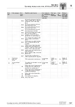
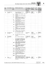
Displays during standard operation
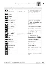
Output stage inhibit
•
Output stage is blocked.
The drive is not actuated by the output stage.
The brake is applied; without brake the motor
coasts to a halt. This FCB is permanently
selected with terminal DI00. But it can be addi-
tionally selected by other sources.
Unassigned
For more information, refer to the chap-
ter parameter description in the project
planning manual.
Unassigned
Unassigned
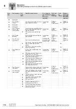
n-control (speed control)
Speed control with internal ramp generator.
Interpolated n-control
Speed control with setpoints cyclically via bus.
The ramp generator is located externally, e.g. in
the higher-level controller.
M-control (torque control)
Torque control
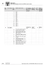
Interpolated M-control
Torque control with setpoints cyclically via bus.
Position control
Positioning mode with internal ramp generator.
Interpolated position control
Positioning mode with setpoints cyclically via
bus. The ramp generator is located externally,
e.g. in the higher-level controller.
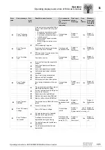
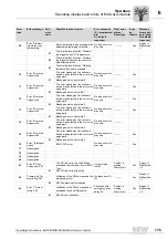
Limit switch (HW & SW)
enable or approach
This FCB is activated by the firmware when the
limit switch is hit.
Reference travel
The drive performs reference travel.
Stop
Deceleration at application limit. This FCB also
becomes active if no other FCB is selected as
default FCB.
Emergency stop
Deceleration at emergency stop limit.
Stop at system limit
Deceleration at system limit.
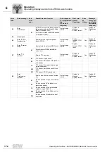
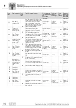
Electronic cam
Electronic cam active.
Synchronous operation
Synchronous operation active.
Calibrate encoder
Encoder commutation for synchronous motors.
Hold control
Position control at current position.
Jog mode
Jog mode active.
Brake test
Brake is tested by applying torque while brake is
closed.
Description
State
Comment / action
Summary of Contents for MOVIAXIS MX
Page 2: ...SEW EURODRIVE Driving the world...
Page 210: ......
Page 211: ...SEW EURODRIVE Driving the world...


