Operating Instructions – MOVIAXIS® MX Multi-Axis Servo Inverter
189
8
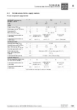
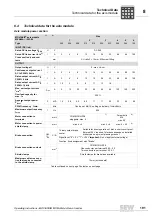
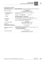
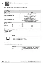
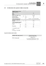
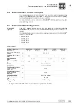
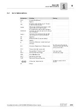
Technical data for the supply module
Technical Data
8.3
Technical data for the supply module
Power component supply module
MOVIAXIS
®
supply module
MXP80A-...-503-00
1)
2)
Size
1
2
3
Type
010
025
3)
050
075
INPUT
Supply voltage AC V
mains
U
V
3
×
380 V ... 3
×
500 V
Rated supply current
AC I
mains
I
A
15
36
72
110
Rated power P
N
P
kW
10
25
50
75
Mains frequency f
mains
f
Hz
50... 60 ±5%
Cross-section and contacts on
connections
mm
2
COMBICON PC4
pluggable, max. 4
COMBICON PC6
pluggable,
max. 16
Screw bolt M8
max. 50
Cross-section and contacts on
shield clamp
mm
2
max. 4
×
4
max. 4
×
10
max. 4
×
50 shielded
OUTPUT (DC LINK)
Rated DC link voltage
4)
U
NZK
U
V
DC 560
Rated DC link current
5)
DC I
NZK
I
A
18
45
90
135
Max. DC link current DC I
ZK max
I
max
A
45
112.5
225
337.5
Overload capacity for max. 1 s
250 %
Brake chopper power
kW
Peak power: 250 %
×
P
N
, continuous power: 0.5
×
P
N
Mean regenerative power
capacity
kW
0.5 x P
N
Cross section
6)
and contacts
mm
CU rails 3
×
14 mm, M6 screw fitting
BRAKING RESISTOR
Minimum permitted braking resis-
tor value R (4-Q operation)
Ω
26
10
5.3
3.5
Cross-section and contacts on
connections
mm
2
COMBICON PC4
pluggable, max. 4
COMBICON PC6
pluggable,
max. 16
M6 screw bolts
max. 16
Cross-section and contacts on
shield clamp
mm
2
max. 4
×
4
max. 4
×
6
max. 4
×
16
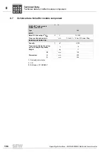
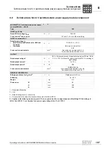
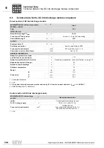
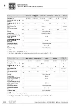
Table continued on next page. Footnotes on next page.
P
i
f
kVA
Hz
n
Summary of Contents for MOVIAXIS MX
Page 2: ...SEW EURODRIVE Driving the world...
Page 210: ......
Page 211: ...SEW EURODRIVE Driving the world...

