192
Operating Instructions – MOVIAXIS® MX Multi-Axis Servo Inverter
8
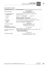
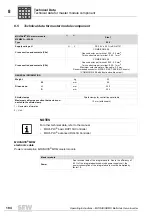
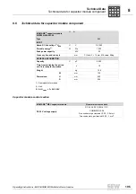
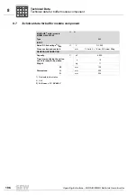
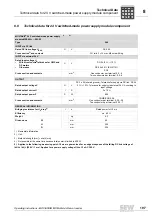
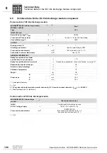
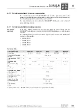
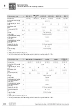
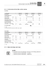
Technical data for the axis module
Technical Data
Notes on brake
control
Permitted load of
brake control and
brake
One complete switching sequence (opening and closing) must not be repeated more of-
ten than a maximum of every two seconds. The brake must remain switched off for at
least 100 ms before it can be switched on again.
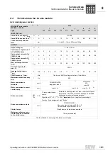
GENERAL INFORMATION
Power loss at nominal
capacity
W
30
60
100
150
210
280
380
450
670
1100
Weight
kg
4.2
4.2
4.2
5.2
5.2
9.2
9.2
9.2
15.6
15.6
W
mm
60
90
90
120
150
210
Dimensions:
H
mm
300
300
400
400
400
400
D
mm
254
1) Nameplate information
2) Unit
3) With simplification: I
NZK
= I
N
(typical motor application)
4) Material strength [mm]
×
width [mm]
5) Indicated values apply to motor operation. Motor and regenerative have the same peak performance.
6) Applies to mains voltage 400 V and 50 Hz / PWM = 8 kHz.
7) PC6 pluggable, one conductor per terminal: 0.5...16 mm
2
; two conductors per terminal: 0.5...6 mm
2
.
8) Max. 4
×
70 mm
2
9) Max. 4
×
50 mm
2
, for cross sections > 50 mm
2
, the cable shield must be connected outside the unit, e.g. DIN rail clamp.
MOVIAXIS
®
axis module
MXA80A-...-503-00
1)
2)
Size
1
2
3
4
5
6
NOTES
Note on tolerance requirement for the brake voltage!
The brake voltage has to be configured. See project planning manual.
P
i
f
kVA
Hz
n
Summary of Contents for MOVIAXIS MX
Page 2: ...SEW EURODRIVE Driving the world...
Page 210: ......
Page 211: ...SEW EURODRIVE Driving the world...


