Operating Instructions – MOVIAXIS® MX Multi-Axis Servo Inverter
193
8
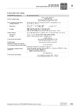
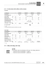
Technical data for the axis module
Technical Data
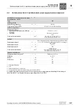
Control section axis module
MOVIAXIS
®
MX axis module
General electronics data
DC 24 V voltage supply
DC 24 V ± 25 % (EN 61131)
COMBICON 5.08
One conductor per terminal: 0.20...2.5 mm
2
Two conductors per terminal: 0.25...1 mm
2
X10:1 and X10:10 binary inputs
Internal resistance
Isolated (optocoupler), PLC compatible (EN 61131), sampling interval 1 ms
R
i
≈
3.0 k
Ω
, I
E
≈
10 mA
Signal level
+13 V...+30 V = "1" = Contact closed
-3 V...+5 V
= "0" = Contact open
meets EN 61131
Function
DIØØ: With fixed assignment "Output stage enable"
DIØ1...DIØ8: Selection option
→
parameter menu
DIØ1 and DIØ2 suitable for touch probe function (latency period < 100 µs)
4 binary outputs
PLC compatible (EN 61131-2), response time 1 ms, short-circuit proof, I
max
= 50 mA
Signal level
"0"=0 V, "1"=+24 V,
Caution: Do not apply external voltage.
Function
DOØØ ... DOØ3: Selection option
→
parameter menu
Cross section and contacts
COMBICON 5.08
One conductor per terminal: 0.20...2.5 mm
2
Two conductors per terminal: 0.25...1 mm
2
Shield clamps
Shield clamps for control lines available
Maximum cable cross section that
can be connected to the shield clamp
10 mm (with sheath)
Connection contacts for safety
functions
Safety relay integrated in unit as option (
→
page 201)
Suitable for operation as device of stop category 0 or 1 according to EN 60204-1 with pre-
vention of restart for safety applications in:
•
Category 3 according to EN 954-1
•
Protection type III according to EN 201
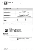
Cross section and contacts
Mini COMBICON 3.5
One conductor per terminal: 0.08 ... 1.5 mm
2
Two conductors per terminal: 0.08 ... 0.75 mm
2
P
i
f
kVA
Hz
n
Summary of Contents for MOVIAXIS MX
Page 2: ...SEW EURODRIVE Driving the world...
Page 210: ......
Page 211: ...SEW EURODRIVE Driving the world...


