20
Operating Instructions – MOVIAXIS® MX Multi-Axis Servo Inverter
3
Standard accessories
Unit Design
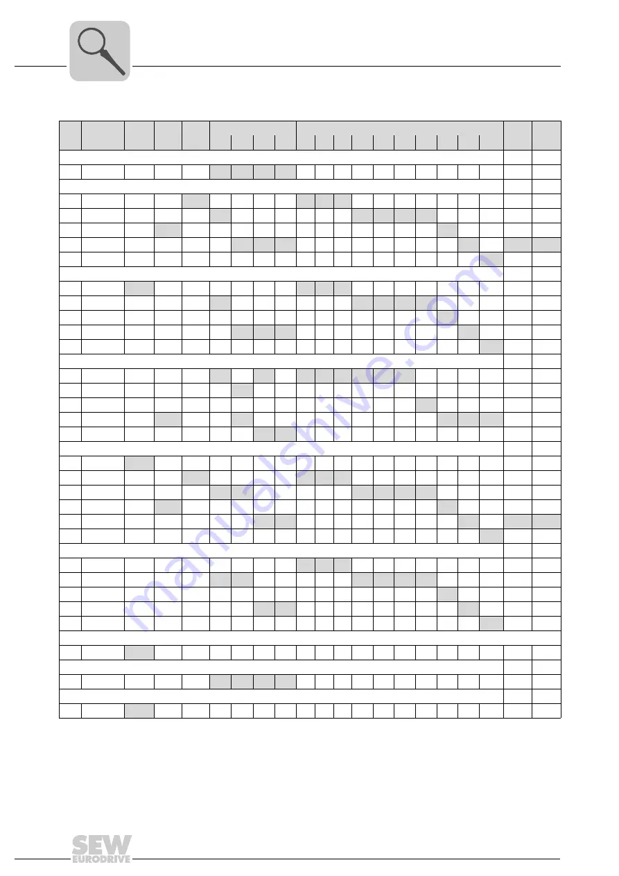
Standard accessory assignment table
No.
Dimen-
sions
1)
1) Length of the cables: Length of the cable without plug
MXM
MXZ
MXS
MXP [kW]
MXA [A]
MXC
MXB
10
25
50
75
2
4
8
12
16
24
32
48
64
100
Touch guard
[1]
2x
2x
2x
2x
DC link connection
[2] 76 mm
3x
3x
3x 3x
[3] 106 mm
3x
3x
3x
3x
3x
[4] 136 mm
2x
3x
[5] 160 mm
3x
3x
3x
3x
3x
3x
[6] 226 mm
3x
Electronics shield clamp
[7] 60 mm
1x
1x
1x 1x
[8] 90 mm
1x
1x
1x
1x
1x
[9] 120 mm
1x
[10] 150 mm
1x
1x
1x
1x
[11] 210 mm
1x
Power shield clamp
[12] 60 mm
1x
1x
1x
1x 1x
1x
1x
1x
[13] 60 mm
2)
2) Clamp with short support, 60 mm wide
1x
[14] 60 mm
3)
3) Clamp with long support, 60 mm wide
1x
[15] 105 mm
1x
1x
1x
1x
1x
[16] 105 mm
1x
1x
24 V supply cable
[17] 40 mm
1x
[18] 50 mm
1x
1x
1x 1x
[19] 80 mm
1x
1x
1x
1x
1x
1x
[20] 110 mm
1x
1x
[21] 140 mm
1x
1x
1x
1x
1x
[22] 200 mm
1x
Signal bus connection cable (suitable for CAN-/ EtherCAT-based system bus)
[23] 200 mm
1x
1x 1x
[24] 230 mm
1x
1x
1x
1x
1x
1x
[25] 260 mm
1x
[26] 290 mm
1x
1x
1x
[27] 350 mm
1x
Connection cable CAN – master module
[28] 520 mm
1x
CAN terminating resistor
[29]
1x
1x
1x
1x
Cable lugs
[30]
3x
Summary of Contents for MOVIAXIS MX
Page 2: ...SEW EURODRIVE Driving the world...
Page 210: ......
Page 211: ...SEW EURODRIVE Driving the world...


