206
Operating Instructions
- MOVIAXIS® MX
Multi-Axis Servo Inverter
Index
Axis modules in XGH version
.......................41
Axis modules in XGS version
.......................41
Axis modules in XIA version
.........................41
Axis modules in XIO version
........................40
P
PDO Editor
Assigning the input buffer to the system
variables
.....................................................155
Parameter setting example
........................153
Setting the FCB parameters
.......................155
Setting the fieldbus interface parameters
...153
Setting the parameters of the control
word and the IN process data
....................154
Structure and data flow
..............................152
Testing the configurations
..........................156
Permitted tightening torque
DC link connection
.......................................99
Permitted tightening torques
Power terminals
............................................99
Signal relay
...................................................99
Signal terminals
............................................99
Permitted voltage supply systems
......................76
PROFIBUS XFP11A module option
Baud rates larger than 1.5 MBaud
...............52
MOVIAXIS
®
/ PROFIBUS connection
..........51
Pin assignment
.............................................51
Setting the station address
...........................52
Terminal assignment
....................................51
R
Rear view of MOVIAXIS
®
MX axis and
supply module housing
.......................................64
Rear view of MOVIAXIS
®
MX DC link
discharge module housing
..................................65
Reference potentials - Notes
..............................89
Reference potentials inside the unit - Notes
.......89
Removing / installing a module
Installing an axis module
............................184
Removing an axis module
..........................181
Safety notes
...............................................180
Repair
...............................................................179
Responses to error acknowledgement
.............160
CPU reset
...................................................160
System restart
............................................160
Warm start
..................................................160
S
Safety functions
....................................................8
Signal bus cables for several axis systems
EtherCAT based system bus
........................71
Signal bus cables to other
SEW units or non-SEW units
EtherCAT-based
...........................................72
Startup of MOVIAXIS
®
MX
Application and system limits
.....................137
Approved encoders
....................................123
Axis configuration
.......................................134
Block diagram speed controller
................. 133
Controller parameters
................................ 139
Current settings
................................. 118
,
141
Download
................................................... 138
Encoder data
............................................. 122
Encoder management
....................... 120
,
142
Encoder management for
non-SEW encoders
................................... 124
Encoder management of SEW encoders
.. 119
Encoder selection
.............................. 120
,
142
Encoder signal processing when
using encoder emulation
........................... 143
Example 1 Rotatory encoder as
distance encoder
....................................... 144
Example 2 Linear encoder as
position encoder
........................................ 146
Example 3 Multi-motor operation
............... 150
Monitoring
.................................................. 131
Motor selection
.......................................... 128
Nameplate
................................................. 129
Selection menu
.......................................... 126
Sequence of a complete startup
................ 128
SEW designation of encoders
................... 121
Speed control parameters
......................... 133
Speed controller setting
............................. 132
System configuration
................................. 127
User-defined units Example
...................... 136
Startup software and its parameters
MOVITOOLS
®
MotionStudio
startup software
......................................... 113
Sequence in case of new startup
.............. 115
Station address
.................................................. 54
Supply module nameplate
................................. 15
Supply system and brake contactors
................. 75
T
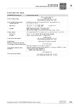
Technical data
Master module - Electronics data
.............. 194
Technical data
DFE24B option for MOVIDRIVE
®
MDX61B
54
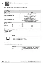
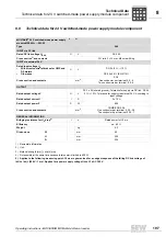
Technical data for 24 V switched-mode
power supply module component
.................... 197
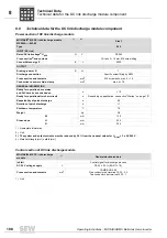
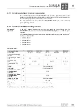
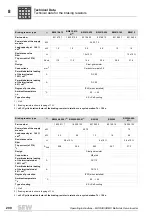
Technical data for braking resistors and filters
Line chokes
............................................... 201
Line filters
.................................................. 201
UL and cUL approval
................................. 199
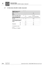
Technical data for buffer module component
... 196
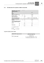
Technical data for capacitor
module component
.......................................... 195
Control section
........................................... 195
Technical data for master module component
. 194
Technical data for the axis module
Control section
........................................... 193
Notes on brake control
.............................. 192
Permitted load of brake control and brake
. 192
Power section
............................................ 191
Summary of Contents for MOVIAXIS MX
Page 2: ...SEW EURODRIVE Driving the world...
Page 210: ......
Page 211: ...SEW EURODRIVE Driving the world...


