Operating Instructions – MOVIAXIS® MX Multi-Axis Servo Inverter
33
3
Unit design of the MOVIAXIS® MXM master module component
Unit Design
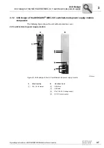
3.11 Unit design of the MOVIAXIS
®
MXM master module component
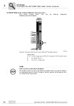
The following figure shows the unit without cover.
MOVIAXIS
®
MXM master module in MOVI-PLC basic version
The master module shown here has the following designation:
MXM80A-000-000-00/DHP11A.
58765axx
Figure 21: Unit design of the master module, MOVI-PLC
®
Basic version
View from front
[1] - [6]
For terminal assignment see "MOVI-PLC
®
basic DHP11B Controller" manual
[7]
Housing grounding point
[8]
X5a, X5b: 24 V voltage supply
[1]
[2]
[4]
[5]
[3]
[6]
[8]
[7]
STOP
Servo inverter can possibly be damaged!
The master module may only be operated when implemented in a system according to
its designated purpose as shown on page 22. Remote operation will damage the mas-
ter module and is not permitted.
Summary of Contents for MOVIAXIS MX
Page 2: ...SEW EURODRIVE Driving the world...
Page 210: ......
Page 211: ...SEW EURODRIVE Driving the world...


