52
Operating Instructions – MOVIAXIS® MX Multi-Axis Servo Inverter
3
PROFIBUS XFP11A fieldbus interface option
Unit Design
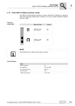
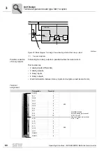
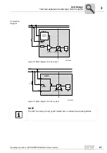
The PROFIBUS interface sends a TTL control signal for a repeater or fiber optic adapter
(reference = pin 9) via pin 4 (CNTR-P).
Baud rates larger
than 1.5 MBaud
The XFP11A option with baud rates > 1.5 MBaud can only be operated with special 12
MBaud PROFIBUS connectors.
Setting the sta-
tion address
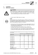
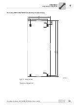
The PROFIBUS station address is set using DIP switches 2
0
... 2
6
on the option card.
MOVIAXIS
®
supports the address range 0...125.
Any change made to the PROFIBUS station address during ongoing operation does not
take effect immediately. The change takes effect when the servo drive is switched on
again (power 24 V OFF/ON).
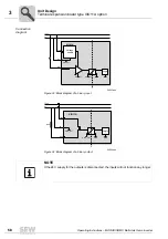
NOTE
If long bus cables are used, the bus stations must have a "hard" common reference
potential.
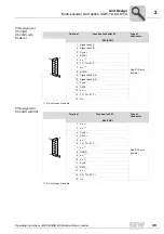
56596AXX
The default setting for the PROFIBUS station address is 4:
2
0
→
Significance: 1
×
0 = 0
2
1
→
Significance: 2
×
0 = 0
2
2
→
Significance: 4
×
1 = 4
2
3
→
Significance: 8
×
0 = 0
2
4
→
Significance: 16
×
0 = 0
2
5
→
Significance: 32
×
0 = 0
2
6
→
Significance: 64
×
0 = 0
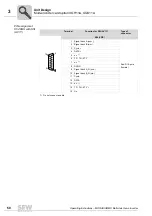
06228AXX
Example: Setting the PROFIBUS station address 17
2
0
→
Significance: 1
×
1 = 1
2
1
→
Significance: 2
×
0 = 0
2
2
→
Significance: 4
×
0 = 0
2
3
→
Significance: 8
×
0 = 0
2
4
→
Significance: 16
×
1 = 16
2
5
→
Significance: 32
×
0 = 0
2
6
→
Significance: 64
×
0 = 0
2
2
2
2
2
2
2
nc
0
1
2
3
4
5
6
2
2
2
2
2
2
2
nc
0
1
2
3
4
5
6
Summary of Contents for MOVIAXIS MX
Page 2: ...SEW EURODRIVE Driving the world...
Page 210: ......
Page 211: ...SEW EURODRIVE Driving the world...


