70
Operating Instructions – MOVIAXIS® MX Multi-Axis Servo Inverter
4
Connection cable EtherCAT-based system bus – optional master module
Installation
4.5
Connection cable EtherCAT-based system bus – optional master module
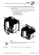
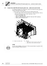
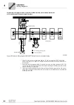
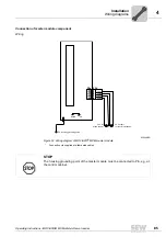
The following describes how the signal bus cables of the EtherCAT-based system bus
must be connected in the axis system.
• Insert the signal bus plugs
[1]
as described in the following (X9a, X9b):
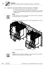
• The RJ-45 plugs on each end of the cable are color coded. Insert them in the fol-
lowing order: red (b)- green (a) - red (b) - green (a) - red (b) ...... .
– red (b): Output (RJ45), X9b
– green (a): Input (RJ45), X9a
– yellow (c): MXM output (RJ45) (MOVI-PLC advanced, UFX41 gateway)
– black (d): MXP input (RJ45), X9a
[b]
[a]
[b]
[a]
[b]
[a]
[d]
[c]
[1]
0
1
0
1
[2]
0
1
[1]
Signal bus connection cable
[2]
LAM switch
•
Switch setting 0: All axis modules except the last one
•
Switch setting 1: Last axis module in the system
STOP
The DIP switch LAM
[2]
must be set to "1" at the last axis module in a system. At all
other axis modules, it must be set to "0".
Summary of Contents for MOVIAXIS MX
Page 2: ...SEW EURODRIVE Driving the world...
Page 210: ......
Page 211: ...SEW EURODRIVE Driving the world...


