90
Operating Instructions – MOVIAXIS® MX Multi-Axis Servo Inverter
4
Terminal assignment
Installation
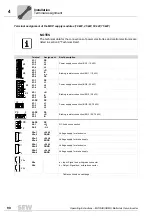
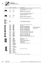
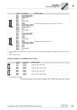
Terminal assignment of the MXP supply modules (10 kW, 25 kW, 50 kW, 75 kW)
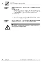
NOTES
The technical data for the connections of power electronics and control electronics are
listed in section 9 "Technical Data".
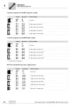
Terminal
Assignment
Brief description
X1:1
X1:2
X1:3
X1:4
PE
L1
L2
L3
Power supply connection (BG1 / 10 kW)
X3:1
X3:2
X3:3
X3:4
+R
-R
n.c.
PE
Braking resistor connection (BG1 / 10 kW)
X1:1
X1:2
X1:3
X1:4
PE
L1
L2
L3
Power supply connection (BG2 / 25 kW)
X3:1
X3:2
X3:3
+R
-R
PE
Braking resistor connection (BG2 / 25 kW)
X1:PE
X1:1
X1:2
X1:3
PE
L1
L2
L3
Power supply connection (BG3 / 50, 75 kW)
X3:PE
X3:1
X3:2
PE
+R
-R
Braking resistor connection (BG3 / 50, 75 kW)
X4:PE
X4:1
X4:2
PE
+U
Z
- U
Z
DC link bus connection
X5a:1
X5a:2
+24 V
E
DGND
Voltage supply for electronics
X5a:3
X5a:4
+24 V
B
BGND
Voltage supply for brake supply
X5b:1
X5b:2
+24 V
E
DGND
Voltage supply for electronics
X5b:3
X5b:4
+24 V
B
BGND
Voltage supply for brake supply
X9a
X9b
a = Input: Signal bus, with green connector
b = Output: Signal bus, with red connector
Table continued on next page
X1
X3
4
4
1
1
X1
X3
4
3
1
1
PE
3
PE
2
PE
2
1
4
1
4
X9a
X9b
Summary of Contents for MOVIAXIS MX
Page 2: ...SEW EURODRIVE Driving the world...
Page 210: ......
Page 211: ...SEW EURODRIVE Driving the world...

