106
Operating Instructions – MOVIAXIS® MX Multi-Axis Servo Inverter
5
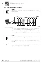
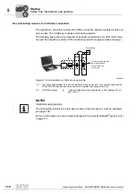
Supply module settings for a CAN-based system bus
Startup
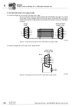
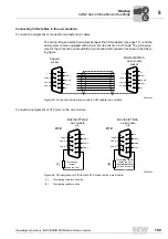
Connecting CAN cables to the supply module:
Connection assignment of connection and extension cables
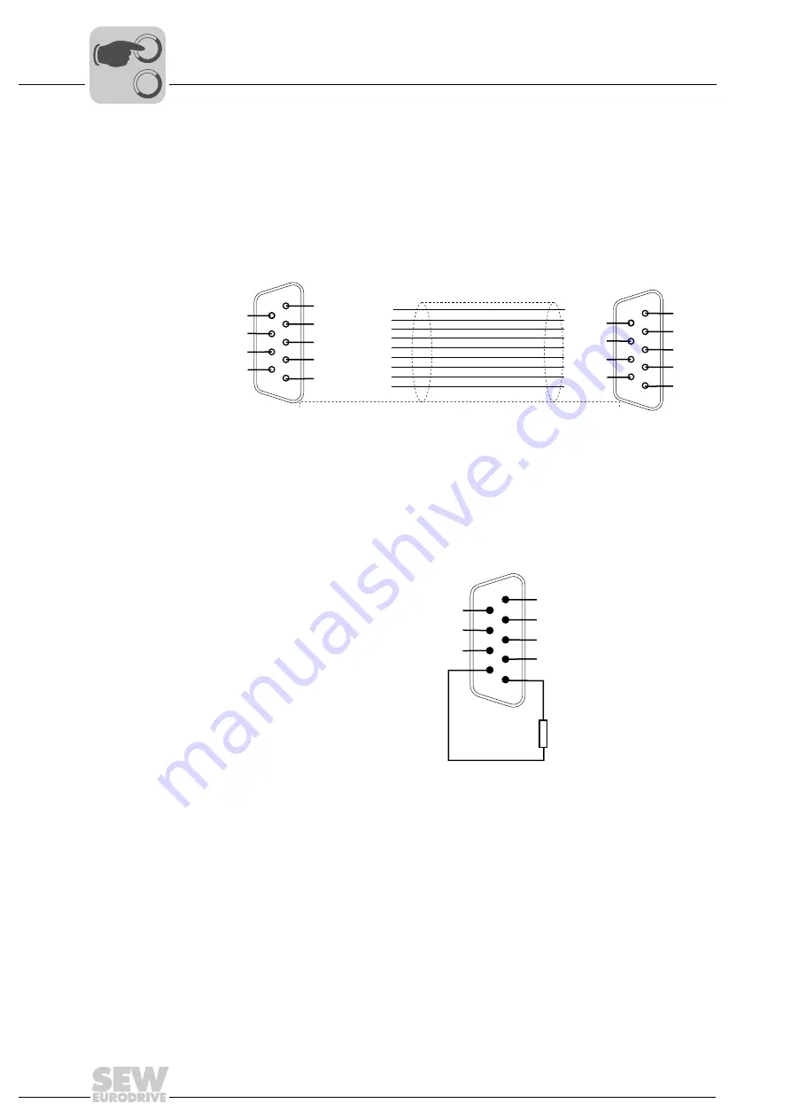
The connecting and extension cables between the CAN adapter (see page 111) and the
axis system comes equipped with a 9 pin D-sub socket on both ends. The pin assign-
ment of the connection cable with the 9 pin D-sub CAN connector is shown in the follow-
ing figure.
Connection assignment of X12 (pin) on the supply module
62479aen
Figure 61: Connection and extension cable CAN adapter and supply module
쵰
쵰
Adapter
MOVIAXIS
®
MXP
supply module
9
n.c.
CAN_H
CAN_H
DGND
8
7
6
1
5
4
3
2
CAN_L
DGND
CAN_L
n.c.
n.c.
socket
9
n.c.
CAN_H
CAN_H
DGND
8
7
6
1
5
4
3
2
CAN_L
DGND
CAN_L
n.c.
n.c.
socket
53923AEN
Figure 62: Pin assignment of the built-in X12 socket at the supply module
6
DGND
CAN_H
CAN_H
7
8
9
5
1
2
3
4
CAN_L
DGND
CAN_L
Terminating
resistor
(inside the unit)
n. c.
Supply module
MOVIAXIS
®
MXP
male
X12
0
0
I
Summary of Contents for MOVIAXIS MX
Page 2: ...SEW EURODRIVE Driving the world...
Page 210: ......
Page 211: ...SEW EURODRIVE Driving the world...

