22
Operating Instructions – MOVIAXIS® MX Multi-Axis Servo Inverter
3
Overview of an axis system
Unit Design
3.7
Overview of an axis system
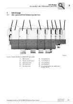
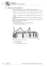
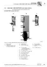
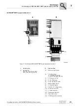
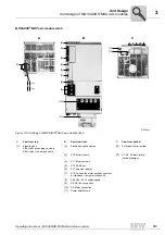
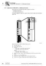
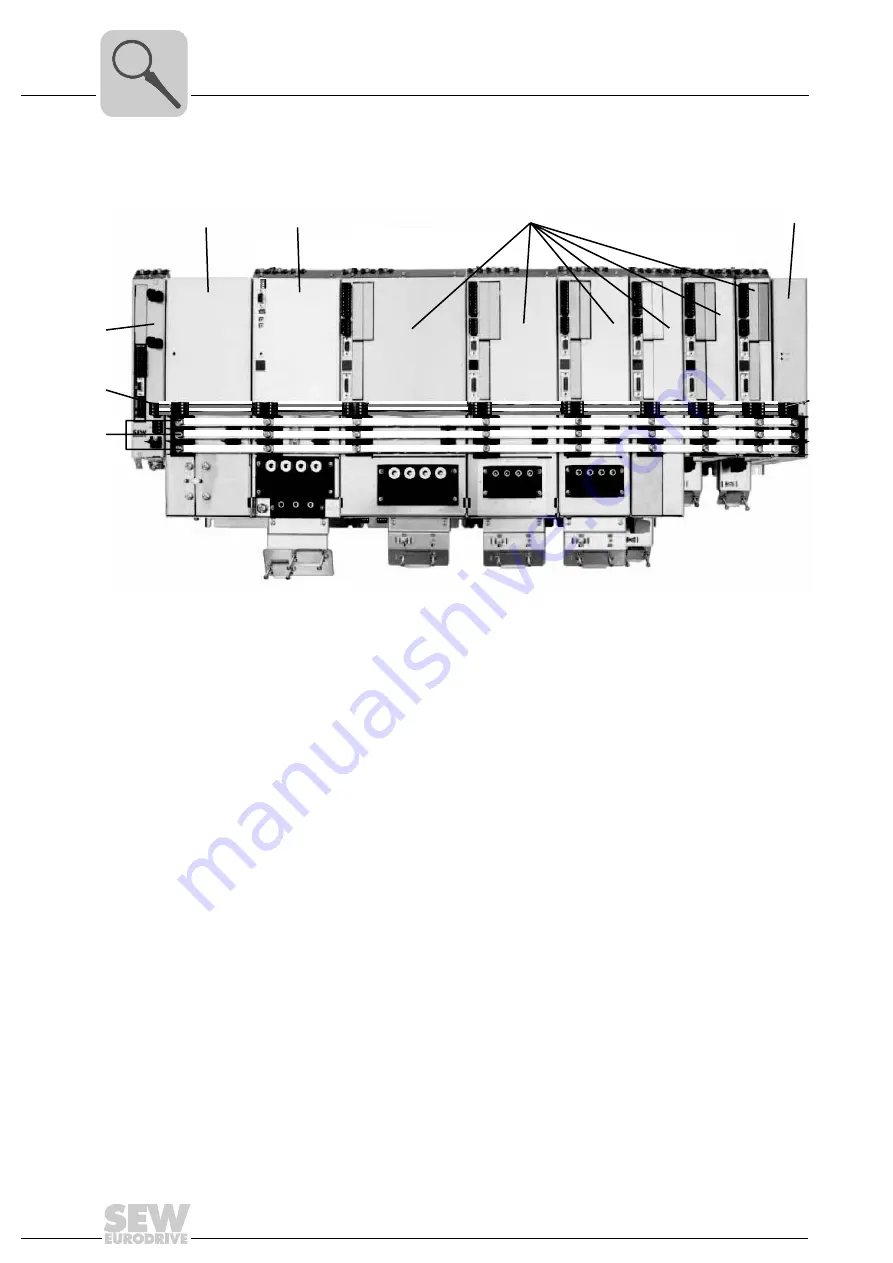
The units are displayed without cover in the following figure.
61507axx
Figure 10: Exemplary representation of the energy supply in the axis system
[1]
[2]
[4]
[3]
[5]
[6]
[7]
[1]
X4: DC link connection
[2]
X5a, X5b: 24 V voltage supply
[3]
Master module
[4]
Capacitor / buffer module
[5]
Supply module BG 3
[6]
Axis modules (size 6 ... size 1)
[7]
24 V switched-mode power supply module
Summary of Contents for MOVIAXIS MX
Page 2: ...SEW EURODRIVE Driving the world...
Page 210: ......
Page 211: ...SEW EURODRIVE Driving the world...

