26
Operating Instructions – MOVIAXIS® MX Multi-Axis Servo Inverter
3
Unit design of MOVIAXIS® MXA axis modules
Unit Design
3.9
Unit design of MOVIAXIS
®
MXA axis modules
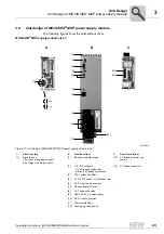
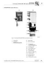
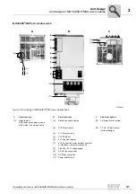
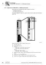
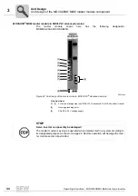
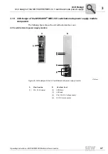
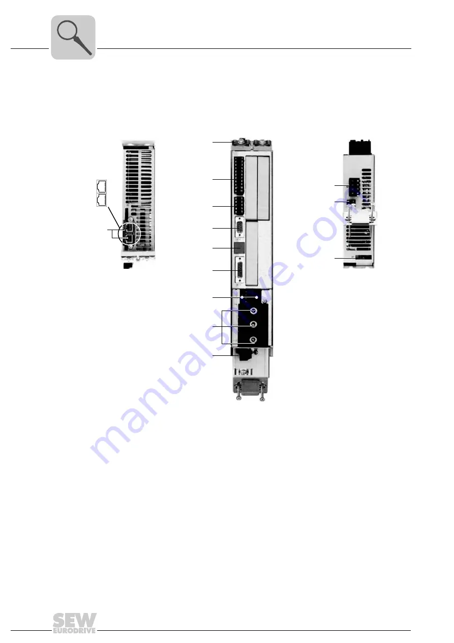
The following figures show the units without cover.
MOVIAXIS
®
MXP axis module size 1
61544axx
Figure 14: Unit design of MOVIAXIS
®
MXA axis module size 1
[2]
[3]
[4]
[5]
[6]
[7]
[8]
[9]
[10]
[11]
[12]
[13]
B
A
C
[1]
X9a
X9b
A
View from top
B
View from front
C
View from bottom
[1]
Signaling bus
X9a: Input, green plug on cable
X9b: Output, red plug on cable
[2]
Electronics shield clamps
[11]
X2: Motor connection
[3]
X10: Binary inputs
[12]
X6: Brake control system
[4]
X11: Binary outputs
[13]
X7: 1 Safety relay (optional
design)
[5]
X12: CAN2 bus
[6]
2 x 7-segment display
[7]
X13: Connection motor encoder (resolver
or Hip temperature sensor)
[8]
X5a, X5b: 24 V voltage supply
[9]
X4: DC link connection
[10]
Power shield clamp
Summary of Contents for MOVIAXIS MX
Page 2: ...SEW EURODRIVE Driving the world...
Page 210: ......
Page 211: ...SEW EURODRIVE Driving the world...


