Operating Instructions – MOVIAXIS® MX Multi-Axis Servo Inverter
67
4
Connection cable for CAN-based system bus with optional master module
Installation
4.2
Connection cable for CAN-based system bus with optional master module
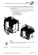
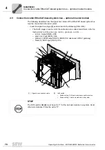
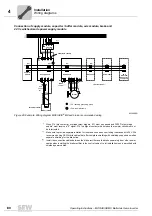
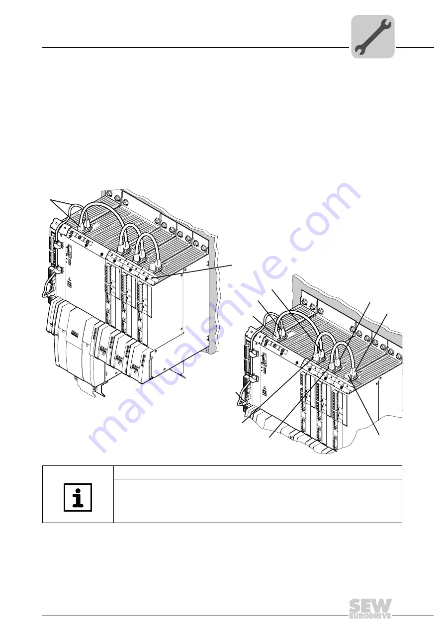
The following describes how the signal bus cables of the CAN system bus must be con-
nected in the axis system.
• Insert the CAN1 signal bus plugs
[1]
as described in the following (X9a, X9b):
• The plugs on each end of the cable are color coded. Insert them in the following
order: red (b)- green (a) - red (b) - green (a) - red (b) ...... .
– red (b): Output (RJ45), X9b
– green (a): Input (RJ45), X9a
– black (c): MXM output (Weidmüller)
– black (d): MXP input (RJ45), X9a
Shield clamps
• Install the cables properly and screw on electronics shield clamps
[2]
.
[2]
[1]
[b]
[a]
[b]
[a]
[b]
[a]
[d]
[c]
[3]
NOTE
Important:
Install a terminating resistor
[3]
in the last axis module of the axis system
(included in the scope of delivery of the supply module).
Summary of Contents for MOVIAXIS MX
Page 2: ...SEW EURODRIVE Driving the world...
Page 210: ......
Page 211: ...SEW EURODRIVE Driving the world...

