78
Operating Instructions – MOVIAXIS® MX Multi-Axis Servo Inverter
4
Wiring diagrams
Installation
4.10 Wiring diagrams
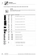
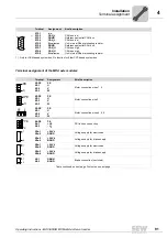
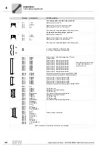
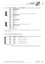
General notes on the wiring diagrams
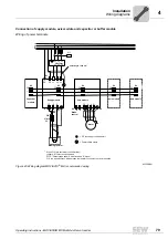
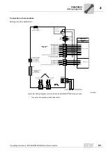
• You will find more information on the connection of power electronics and control
electronics in section "Technical Data", page 187.
• All units within the axis group will have to be connected to each other via the DC link
bus connection (PE, + U
z
, - U
z
), the 24 V bus (X5a, X5b) and the signaling bus (X9a,
X9b).
• The supply system contactor "K11" must be installed between the supply system and
the line filter.
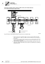
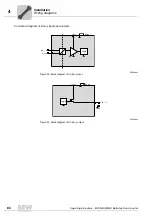
Brake rectifier in
the control cabinet
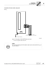
Install the connection cables between the brake rectifier and the brake separately from
other power cables when installing the brake rectifier in the control cabinet. Joint instal-
lation is permitted with shielded power cables only.
NOTES
• Connect the brake rectifier using a separate supply system lead.
• Supply via the motor voltage is not permitted.
NOTES
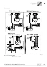
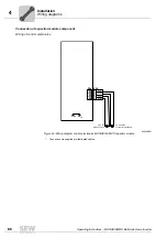
• If the brake connection and the motor connection are combined in one power cable,
the brake line must be shielded separately. The shielding of the power cable and
the brake cable must be connected with PE on the motor and servo inverter.
• Use a shielded cable as brake cable with separate installation of the brake cable.
• Observe the different project specifications for determining the length of brake cable
and motor cable.
Summary of Contents for MOVIAXIS MX
Page 2: ...SEW EURODRIVE Driving the world...
Page 210: ......
Page 211: ...SEW EURODRIVE Driving the world...


