Operating Instructions – MOVIAXIS® MX Multi-Axis Servo Inverter
99
4
UL compliant installation
Installation
4.14 UL compliant installation
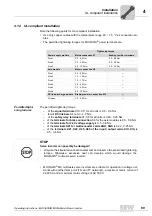
Note the following points for UL-compliant installation:
• Use only copper cables with the temperature range 60 / 75 °C as connection ca-
bles.
• The permitted tightening torques for MOVIAXIS
®
power terminals are:
Permitted tight-
ening torques
The permitted tightening torque
– of the
signal terminals
X10, X11 for all units is 0.5 - 0.6 Nm.
– for all
DC link bars
X4 is 3.0 - 4.0 Nm.
– of the
safety relay terminals
X7, X8 for all units is 0.22 - 0.25 Nm.
– of the
terminals for brake connection
X6 for the axis modules is 0.5 - 0.6 Nm.
– of the
terminals for 24 V voltage supply
is 0.5 - 0.6 Nm.
– of the
terminals X61 for multi-encoder cards XGH, XGS
is 0.22 - 0.25 Nm.
– of the
terminals X21, X22, X25, X26 of the input / output cards XIO, XIA
is
0.5 - 0.6 Nm
• MOVIAXIS
®
MX multi-axis servo inverters are suitable for operation in voltage net-
works with earthed star point (TN and TT networks), a maximum mains current of
42,000 A and a maximum mains voltage of AC 500 V.
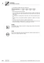
Tightening torque
Power supply module
Mains connection X1
Braking resistor terminals
Size 1
0.5 - 0.6 Nm
0.5 - 0.6 Nm
Size 2
3.0 - 4.0 Nm
3.0 - 4.0 Nm
Size 3
6.0 - 10.0 Nm
3.0 - 4.0 Nm
Axis module
Motor connection X2
---
Size 1
0.5 - 0.6 Nm
---
Size 2
1.2 - 1.5 Nm
---
Size 3
1.5 - 1.7 Nm
---
Size 4
3.0 - 4.0 Nm
---
Size 5
3.0 - 4.0 Nm
---
Size 6
6.0 - 10.0 Nm
DC link discharge module
Braking resistor connection X15
---
All sizes
3.0 - 4.0 Nm
---
STOP
Servo inverter can possibly be damaged!
• Only use the stipulated connection elements and observe the prescribed tightening
torques. Otherwise, excessive heat can develop which would damage the
MOVIAXIS
®
multi-axis servo inverter.
Summary of Contents for MOVIAXIS MX
Page 2: ...SEW EURODRIVE Driving the world...
Page 210: ......
Page 211: ...SEW EURODRIVE Driving the world...

