8
Electrical installation
Safe digital inputs (F-DI.)
Manual – MOVISAFE
®
CS..A Safety Card
52
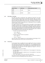
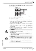
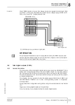
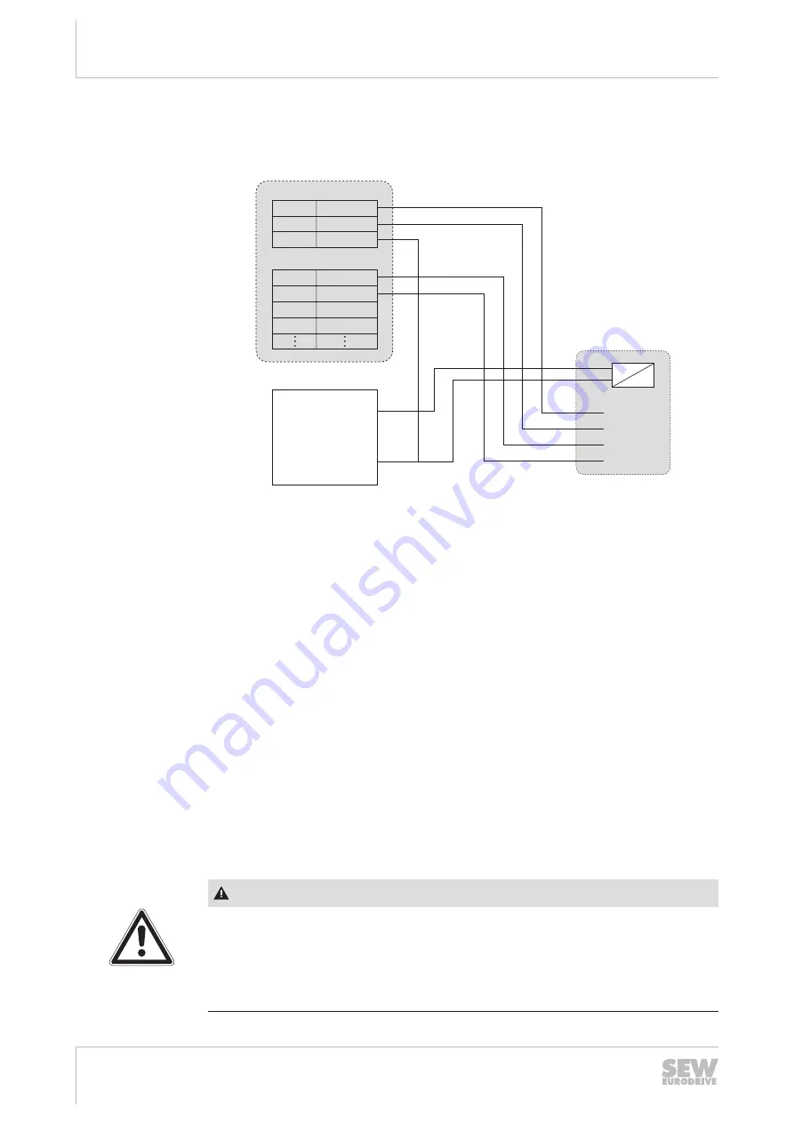
The following figure shows the MOVISAFE
®
CS..A safety card with an active sensor
(dual-channel).
DC 24 V
0 V
[6]
9
10
3, 4, 7, 8
F-SS0
F-DI00
F-DI01
F-DI02
F-DI03
F-SS1
GND
1
5
2
6
X60
X60
MOVISAFE
®
CS..A
Pulse1 [2]
Pulse2 [3]
Out1 [4]
Out2 [5]
+24V
0V
[1]
9007207666490251
[1] Active dual-channel sensor
[2] Supply of output 1 (Out1)
[3] Supply of output 2 (Out2)
[4] Safe digital output 1
[5] Safe digital output 2
[6] External DC 24 V voltage supply
Operation with activated crossfault monitoring
The following errors are detected:
•
Crossfault between every digital input line F-DI. and a 24 V supply voltage.
•
Crossfault between a digital input line F-DIx and another digital input line F-DIy,
which is assigned to another sensor supply, if at least the associated switch con-
tact of the other digital input F-DIy is closed.
•
Crossfault between a digital input line FDI and a sensor supply line not assigned to
the input F-DI.
•
Crossfault between a sensor supply line F-SS and a 24 V supply voltage if the di-
gital input F-DI is assigned to the sensor supply and the switch contact belonging
to F-DI is closed.
•
Crossfault between the sensor supply lines F-SS themselves if the switch contact
belonging to the digital input F-DI is closed.
WARNING
The MOVISAFE
®
CS..A safety card cannot detect a short circuit between an F-SS.
sensor supply and an associated safe digital input F-DI. (bridging of the sensor).
Severe or fatal injuries.
•
Make sure that a short circuit between the sensor supply F-SS. and an associ-
ated safe digital input F-DI. is not possible.
24842532/EN – 04/2018

