background image

3

Safety concept

Drive safety functions

Manual – MOVISAFE

®

 CS..A Safety Card

23

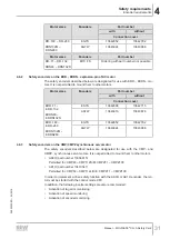
3.7.6

SOS – Safe Operating Stop

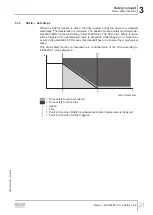
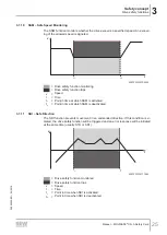
The  SOS  function  prevents  the  motor  from  deviating  from  the  stop  position  by  more
than a specified value. The drive inverter delivers the power to keep the motor in posi-
tion. If the specified value is exceeded, the drive safety function will be triggered and
an error response will be initiated at the same time.

t

1

t

2

t

V

9007201225700491

= Drive safety function monitoring
= Drive safety function trips

v

= Speed

t

= Time

t

1

= Point in time when SOS is triggered.

t

2

= Point in time when SOS is deactivated.

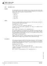
3.7.7

SLA – Safely Limited Acceleration

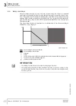
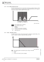
The  SLA  function  prevents  a  movement  from  exceeding  a  specified  acceleration
value. If the permitted acceleration limit is exceeded, the drive safety function will be
triggered and an error response will be initiated at the same time.

t

1

t

2

t

V

9007201225705355

= Drive safety function monitoring
= Drive safety function trips

v

= Speed

t

= Time

t

1

= Point in time when SLA is activated.

t

2

= Point in time when SLA is deactivated.

24842532/EN – 04/2018

Summary of Contents for Movidrive CS**A Series

Page 1: ...24842532_0418 Drive Technology Drive Automation System Integration Services Manual MOVIDRIVE modular MOVIDRIVE system MOVISAFE CS A Safety Card Edition 04 2018 24842532 EN...

Page 2: ...SEW EURODRIVE Driving the world...

Page 3: ...3 2 6 1 Restrictions of use 13 2 7 Electrical installation 13 2 8 Definitions 14 2 9 Startup operation 14 3 Safety concept 15 3 1 General information 15 3 2 Notes on stop categories 15 3 3 Pluggable s...

Page 4: ...Scope of delivery 34 6 3 Compatibility 35 6 4 MOVISAFE CSS21A CSB21A 36 6 5 MOVISAFE CSB31A CSS31A 37 7 Mechanical installation 38 7 1 Before you start 38 7 2 Installation of the MOVISAFE CS A safety...

Page 5: ...tion of the drive safety functions 64 9 5 1 Prerequisites 64 9 5 2 Parameterization procedure 64 9 5 3 Encoder error muting 65 9 5 4 Test mode 66 9 6 Startup of the fieldbus and the higher level F PLC...

Page 6: ...rive safety function via safe communication 88 11 1 6 Response time in case of limit value violation in independent operation 91 11 1 7 Response time in case of limit value violation with safe communi...

Page 7: ...Card 7 13 4 Sensor supply 105 13 5 Safe digital outputs 105 13 6 Characteristic safety values 106 13 6 1 Drive safety functions without encoder evaluation 106 13 6 2 Drive safety functions with encode...

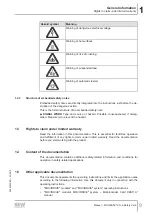
Page 8: ...e shows the grading and meaning of the signal words for safety notes Signal word Meaning Consequences if disregarded DANGER Imminent hazard Severe or fatal injuries WARNING Possible dangerous situatio...

Page 9: ...3 Rights to claim under limited warranty Read the information in this documentation This is essential for fault free operation and fulfillment of any rights to claim under limited warranty Read the d...

Page 10: ...Functional Safety for Synchronous Motors 1 6 Product names and trademarks The brands and product names in this documentation are trademarks or registered trademarks of their respective titleholders 1...

Page 11: ...on the product pay attention to the following regula tions conditions documentation and information National and regional safety and accident prevention regulations Warning and safety signs on the pro...

Page 12: ...is intended for installation in inverters The product is a programmable safety control for manufacturing safety cutoffs and functions The product is intended for use In emergency off devices As a saf...

Page 13: ...must not be mechanically damaged or destroyed Observe the notes in chapter Mechanical installation 2 38 in the documenta tion 2 6 1 Restrictions of use The following applications are prohibited unles...

Page 14: ...s during operation Mechanical blocking or internal drive safety functions of the product can cause a mo tor standstill Eliminating the cause of the problem or performing a reset may result in the driv...

Page 15: ...ed off irrespective of the setpoints set With stop category 1 the MOVISAFE CS A safety card monitors the stopping of the drive and subsequently interrupts the supply of power to the motor With SS1 c t...

Page 16: ...res that the para meterization tool Assist CS is connected to the correct device The user is authentic ated via the entry of a password 3 5 Report and safety check The acceptance report can be created...

Page 17: ...1A and CSS31A safety cards can reliably monitor motion functions in conjunction with the following safety encoders ES7S EG7S AS7W AG7W AK0H AK1H EI7C FS The MOVISAFE CS A safety card switches off the...

Page 18: ...r As a result the drive cannot generate torque This drive safety function corres ponds to a non controlled stop according to EN 60204 1 stop category 0 t V t1 9007201225613323 Drive safety function tr...

Page 19: ...y function is triggered when the monitored deceleration is exceeded or when standstill is reached This drive safety function corresponds to a controlled stop of the drive according to EN 60204 1 stop...

Page 20: ...rding to EN 60204 1 stop category 1 t2 t1 t V t 9007201225618443 Drive safety function monitored Drive safety function trips v Speed t Time t1 Point of time when SS1 c is activated and motor decelerat...

Page 21: ...ety function will be triggered if the deceleration value is exceeded while stopping or if movement occurs during standstill STO means that standstill has to be ensured by a mechanical brake This drive...

Page 22: ...standstill has to be ensured by a mechanical brake This drive safety function corresponds to a controlled stop of the drive according to EN 60204 1 stop category 2 t1 t2 t t V 9007201429937291 Drive...

Page 23: ...700491 Drive safety function monitoring Drive safety function trips v Speed t Time t1 Point in time when SOS is triggered t2 Point in time when SOS is deactivated 3 7 7 SLA Safely Limited Acceleration...

Page 24: ...rive safety function trips v Speed t Time t1 Time when SLS is activated t2 Time when SLS is deactivated 3 7 9 SSR Safe Speed Range The SSR function prevents the speed of the drive from exceeding a spe...

Page 25: ...t1 Point in time at which SSM is activated t2 Point in time at which SSM is deactivated 3 7 11 SDI Safe Direction The SDI function prevents movement in an unintended direction If this condition is vi...

Page 26: ...S2 S3 9007201225720459 Drive safety function monitoring Drive safety function trips v Speed s Distance s1 s2 Point in time when SLI is activated s2 s3 Point in time when SLI is deactivated s Safe inc...

Page 27: ...he PC and the Assist CS para meterization tool are not safety related and therefore possibly not error free the safety concept prescribes the following measures Identification of the MOVISAFE CS A The...

Page 28: ...ensors that are supplied by a separate voltage supply and connec ted to the MOVISAFE CS A safety card The encoder cable must not carry a TF signal when connecting an EI7C FS built in encoder to the MO...

Page 29: ...d pairs as follows UB and GND A and A B and B The encoder cable may exhibit the following maximum capacitances per unit length Capacitance per unit length core core CA 70 pF m Capacitance per unit len...

Page 30: ...response time may not be exceeded The user must ensure implementation of the requirements of the required performance level pursuant to EN ISO 13849 1 4 5 Requirements for stopping in an emergency to...

Page 31: ...RN132S ES7S 13642898 13642715 AS7W 13643916 13643878 EDR 160 EDR 280 EDRN132M EDRN280 EG7S 13642952 13642782 AG7W 13643924 13643886 4 6 3 Safety encoders on the CMP CMPZ synchronous servomotor The saf...

Page 32: ...termines the average speed over the last 4 recorded encoder increments The response time of the encoder evaluation is thus dependent on the actual speed The error in the calculated speed value equals...

Page 33: ...ocking device The additional preventive measures must cover the danger zone until no further danger to personnel exists As an alternative you must equip the drive with a safety brake The additional pr...

Page 34: ...y card CS Series C MOVI C option card S Safety x Function B Basic Stop functions without encoder S Standard Speed functions with a safe encoder x Hardware design 1 MOVITRAC 2 MOVIDRIVE without 2nd Enc...

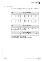
Page 35: ...xx xx xx 13 00 xx xx xx 11 00 3 xx xx xx 13 00 xx xx xx 11 00 4 xx xx xx 13 00 xx xx xx 11 00 5 xx xx xx 13 00 xx xx xx 11 00 6 xx xx xx 13 00 xx xx xx 11 00 The xx entries have no effect on compatibi...

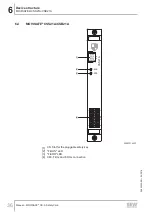
Page 36: ...A Safety Card 36 6 4 MOVISAFE CSS21A CSB21A MOVISAFE CSS21A CSB21A 4700 0015 E223 282D XS X60 CSS21A F RUN F ERR 14 13 1 2 1 2 3 4 20367319307 1 XS Slot for the pluggable safety key 2 F RUN LED 3 F E...

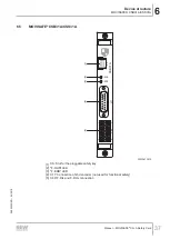
Page 37: ...SS31A MOVISAFE CSB31A CSS31A 0800 0015 DF1F 652D XS X60 X17 CSB31A F RUN F ERR 1 9 8 15 14 13 1 2 1 2 3 4 5 20370612875 1 XS Slot for the pluggable safety key 2 F RUN LED 3 F ERR LED 4 X17 Connection...

Page 38: ...allation of the MOVISAFE CS A safety card Installation of the MOVISAFE CS A safety card The MOVISAFE CS A safety card can be installed only in the following inverters Inverter MO VISAFE CS 21A MO VISA...

Page 39: ...CS A Safety Card 39 3 Remove the safety cover 1 from the front of the application inverter 1 2 1 5 4 3 2 1 5 4 3 2 1 27021611749935499 4 Remove the plastic cover 1 at the card slot 1 1801441249519207...

Page 40: ...torque 0 6 0 8 Nm 18014412495199371 7 Install the safety cover at the front side of the application inverter 7 4 Installation of the MOVISAFE CS A safety card MOVIDRIVE system Installation of the MOV...

Page 41: ...uit able measures for equipotential bonding include for example the use of a dis charge strap or wearing conductive shoes 3 Remove the safety cover 1 from the front of the application inverter 1 2 1 5...

Page 42: ...ard MOVIDRIVE system Manual MOVISAFE CS A Safety Card 42 5 Take the MOVISAFE CS A safety card 1 and insert it in the slot with slight pres sure 1 15160623243 6 Screw the safety card tight with the spe...

Page 43: ...tion Installation of the MOVISAFE CS A safety card MOVIDRIVE system Manual MOVISAFE CS A Safety Card 43 7 Install the safety cover 1 at the front of the application inverter 1 5 4 3 2 1 2 1 1457845530...

Page 44: ...VE modular system No voltage may be connected 8 2 Installation instructions To guarantee electrical safety and fault free operation you must observe the general installation instructions and the notes...

Page 45: ...5 F DI02 Safe digital input F DI02 X60 6 F DI03 Safe digital input F DI03 X60 7 GND Reference potential for safe inputs outputs X60 8 GND Reference potential for safe inputs outputs X60 9 F SS0 DC 24...

Page 46: ...onnection variants might be limited de pending on the sensor type Note in addition the chapter Requirements for external sensors and actuators as well as the general installation regulations Possible...

Page 47: ...acts are moved into the opened activated state after the occurrence of the discrepancy error so that the two input signals assume the required state for the switch test Connection type Dual channel eq...

Page 48: ...itoring is not active e g for sensors with OSSD output the sensors can be supplied either from F SS0 F SS1 or from another 24 V supply that has the same ground reference WARNING Danger due to incorrec...

Page 49: ...input F DI Crossfault between a sensor supply line F SS and a 24 V supply voltage if the di gital input F DI is assigned to the sensor supply and the switch contact belonging to F DI is closed Crossf...

Page 50: ...riant 2 Dual channel contact equipped sensor in equivalent connection variant Operation with activated crossfault monitoring The following errors are detected Crossfault between every digital input li...

Page 51: ...alent connection variant the NC contact is connected to the sensor supply F SS0 8 5 7 Active sensors dual channel When connecting a dual channel sensor with additional voltage supply the voltage is su...

Page 52: ...and another digital input line F DIy which is assigned to another sensor supply if at least the associated switch con tact of the other digital input F DIy is closed Crossfault between a digital input...

Page 53: ...3 WARNING If crossfault monitoring is deactivated the MOVISAFE CS A safety card cannot detect crossfaults in the cabling Severe or fatal injuries Make sure that crossfaults are not possible at the saf...

Page 54: ...on its own The faults detected in the cabling depend on the diagnostic function of the used sensor For OSSD sensors the following two connection variants are possible examples Variant 1 If contact equ...

Page 55: ...F SS sensor supply lines can provide 8 6 Safe digital outputs F DO 8 6 1 General information The processing of the safe digital outputs takes place inside the MOVISAFE CS A safety card in dual channe...

Page 56: ...onic assemblies as buffer capacitors If the capacitive load has a diode in series to its input the maximum load capacity permitted is 12 F This diode is often installed as polarity protection diode in...

Page 57: ...cted Operating the devices without line diagnostics is therefore not recommended WARNING When line diagnostics is deactivated the MOVISAFE CS A safety card cannot de tect a short circuit between a sou...

Page 58: ...nostics The MOVISAFE CS A safety card detects the following faults in the external cabling when the output is switched on or off Short circuit between sourcing output and a supply voltage that lies wi...

Page 59: ...multaneously This can be achieved via a drive safety function STO SBC assigned to both outputs or via the secure process output data F PA F DO00 and F DO01 The MOVISAFE CS A safety card detects the fo...

Page 60: ...s activated Short circuit between different sourcing outputs Short circuit between the P output and the reference potential 0 V Overload at every output Wire break F DO if activated WARNING In case of...

Page 61: ...er signal The MOVISAFE CS A safety card detects interruptions and crossfaults in the en coder line If a fault occurs the MOVISAFE CS A activates the drive safety function STO in the MOVIDRIVE modular...

Page 62: ...stem the FCB 01 Output stage inhibit function block must be selected in the MOVISUITE parameter tree under Functions Drive functions In FCB 01 Output stage inhibit the Close brake with STO parameter m...

Page 63: ...supported by a acceptance protocol generated in the Assist CS parameterization tool For startup perform the following steps 1 Parameterization of drive safety functions in the Assist CS parameterizati...

Page 64: ...neering interface to the MOVIDRIVE device RS485 Ethernet etc 3 Start the Assist CS parameterization tool Start the Assist CS parameterization tool from the MOVISUITE interface A window opens with a pr...

Page 65: ...hout any errors you can start up the standard functions and if required make the connection to the higher level safety controller F PLC 9 5 3 Encoder error muting WARNING The active function Encoder e...

Page 66: ...limit value viola tion activation of drive safety function STO 5 minutes after activation 9 6 Startup of the fieldbus and the higher level F PLC Note that this startup option supports only the safe f...

Page 67: ...mmunication occurs in the Safe state operating state All safe digital inputs and outputs are disconnected from power The Safe state operating state can be resolved only by deactivation and reactivatio...

Page 68: ...verified by exceeding each limit value and then triggering the defined state safe state STO brake de en ergized You may must take this into account in the machine and system controls 9 8 2 Creating an...

Page 69: ...ate you must ensure that the system is in idle state and no dangerous movements can be performed No drive safety function is approved in the delivery state of the safety card The safety card permanent...

Page 70: ...re of the MOVI C CONTROLLER UHX84A R UHX85A R in MOVISUITE in the Device data Main components System package section Firmware V2 0 Release 201703xxxx March 2017 and older supports up to 8 safety cards...

Page 71: ...ble Data type Function Presetting Variables that the user can control DBX0 0 F00008_198 PASS_ON BOOL 1 Activate pas sivation 0 DBX0 1 F00008_198 ACK_NEC BOOL 1 Acknowledg ment required for reintegra t...

Page 72: ..._REI In order to reintegrate the safety card after the fault has been corrected user acknow ledgment with positive edge at the variable ACK_REI is required Acknowledgment is possible only if variable...

Page 73: ...dgment of the locked digital inputs 1 Acknowledgment has been requested re acknow ledgment by edge 0 1 7 Acknow ledgment error 0 No acknowledgment Edge 0 1 Acknowledgment of the pending errors 1 Ackno...

Page 74: ...erve 7 Reserve 10 3 2 CSB31A profile variant Technology Bus F DO Byte Bit Name Value Description 0 0 STO1 0 The STO drive safety function is selected 1 The STO drive safety function is not selected 1...

Page 75: ...DO01 0 Output F DO01 is not selected The safety related output is open 1 Output F DO01 is selected The safety related output is closed 2 Reserve 3 Reserve 4 Reserve 5 Reserve 6 Reserve 7 Reserve 2 0...

Page 76: ...r control muting 0 Test mode for drive safety functions is not selected 1 Test mode for drive safety functions is selected 6 Acknow ledge F DI 0 No acknowledgment Edge 0 1 Acknowledgment of the locked...

Page 77: ...ted 6 SLI1 0 The SLI1 drive safety function is selected 1 The SLI1 drive safety function is not selected 7 SLI2 0 The SLI2 drive safety function is selected 1 The SLI2 drive safety function is not sel...

Page 78: ...F PA otherwise an error in the encoder system leads im mediately to an encoder error 10 4 F process input data 10 4 1 CSB21A profile variant Technology Bus STO Byte Bit Name Valu e Description 0 0 STO...

Page 79: ...F DI02 no voltage or error is present 1 Process value of digital safe digital input F DI02 voltage is present 3 F DI03 0 Process value of digital safe digital input F DI03 no voltage or error is prese...

Page 80: ...safety card 7 Error state 0 The safety card is in error free operation 1 At least one warning is active in the safety card 1 0 F DI00 0 Process value of digital safe digital input F DI00 no voltage o...

Page 81: ...Sx1 drive safety function is not active or an error has occurred 1 The SSx1 drive safety function is active 3 SSx2 0 The SSx2 drive safety function is not active or an error has occurred 1 The SSx2 dr...

Page 82: ...n has determined the ex ceeding of a limit value 1 At least one selected drive safety function has determined the exceeding of a limit value or can not execute limit value monitoring as a con sequenti...

Page 83: ...tal input F DI03 voltage is present 4 Reserve 5 Reserve 6 Reserve 7 Reserve 2 0 SOS1 0 The SOS1 drive safety function is not active or an error has occurred 1 The SOS1 drive safety function is active...

Page 84: ...ction is active 5 SSR2 0 The SSR2 drive safety function is not active or an error has occurred 1 The SSR2 drive safety function is active 6 Reserve 7 Reserve 4 0 SLA1 0 The SLA1 drive safety function...

Page 85: ...FS pro tocol the value 0 is written for Error State 10 5 Acknowledgment of safety card 10 5 1 Acknowledgment of PROFIsafe data exchange The PROFIsafe communication must be error free for safe data exc...

Page 86: ...afety function in your application and determine the maximum response time for each case taking into account the relevant manufacturer data Observe in particular the information contained in the safet...

Page 87: ..._VEL Filter time speed 8708 4 1 n_Actual T_Task T_Sys Response time encoder error Deactivation F DO_STO F DOx 8 ms Setting error status F PE 12 ms 11 1 2 Safe digital input F DI All response times mus...

Page 88: ...ssing_F DI T_Sys SSx b monitoring delay t2 8706 9 Actual_speed SSx b delay a 8706 10 SSx x jerk time2 t3 8706 11 SS1 c T_InputProcessing_F DI T_Sys SSx c delay t1 8706 8 brake application time1 8706 1...

Page 89: ...2 T_Sys SSx c delay t1 8706 8 brake application time1 8706 15 Via F DI T_InputProcessing_F DI 2 T_Sys SSx c delay t1 8706 8 brake application time1 8706 15 SS2 c Via F PA T_InputProcessing_F PA T_Sys...

Page 90: ...s monitoring delay t2 8706 53 Via F DI T_InputProcessing_F DI T_Sys monitoring delay t2 8706 53 SDI Via F PA T_InputProcessing_F PA T_Sys Via F DI T_InputProcessing_F DI T_Sys SLI Via F PA T_InputProc...

Page 91: ...STO T_ENC_VEL T_Sys SS1 c T_ENC_VEL T_Sys SSx c delay t1 8706 8 brake application time1 8706 15 SS2 c T_ENC_VEL T_Sys SSx c delay t1 8706 8 SS1 b T_ENC_VEL T_Sys SSx b monitoring delay t2 8706 9 brak...

Page 92: ...b delay a 8706 10 SSx x jerk time2 t3 8706 11 SSM T_ENC_VEL T_Sys SSR with parameter ized error response STO T_ENC_VEL 2 T_Sys SS1 c T_ENC_VEL 2 T_Sys SSx c delay t1 8706 8 brake application time1 87...

Page 93: ...2 Calculation factor formula symbol Calculation specification response time Response time T_InputProcessing_F DI_Deselection T_InputProcessing_F DI_Deselection 16 ms 11 1 9 Deselection of a drive safe...

Page 94: ...come void if the user modifies the device internally e g ex change of components welding parts 12 2 Waste disposal Observe the applicable national regulations Dispose of materials separately in ac cor...

Page 95: ...more of the following constraints The safety card controls inverters Test mode Off Device off 12 3 2 F ERR LED The following table shows the states of the F ERR LED LED status Meaning Red Critical er...

Page 96: ...and outputs as applicable System error Entry in fault memory and safe state of digital in puts and outputs Critical error Entry in fault memory and safe state of digital in puts and outputs No safe c...

Page 97: ...arameterized this always leads to an en coder error In addition the corresponding error code is transferred for the encoder error that occurred The acknowledgment of the encoder error with activated d...

Page 98: ...e communication is suspen ded In addition the corresponding error code is transferred for the critical error that oc curred Error messages If there is an error in the safety card the inverter indicate...

Page 99: ...g type See error status Subcomponent safety card Subfault 46 51 Description Error Response Emergency stop and output stage inhibit with self reset Cause Measure The safety option signals a subcomponen...

Page 100: ...e dispatched diagnostic alarm if the Diagnostic alarm as sembly parameter is enabled for the safety card in the F host per configuration De pending on the fieldbus used PROFIBUS DP or PROFINET IO the...

Page 101: ...that do not directly trigger an error response of the CS A safety card Essentially these are the message Power On primary error 66 and sub error 100 and the message Acknowledgment mes sage primary er...

Page 102: ...has been loaded The MOVISAFE CS A safety card is subsequently in the same state that it was in before the device replacement This means that the MOVISAFE CS A safety card will be in the Accepted stat...

Page 103: ...em operating instructions 0 C 40 C without derating 40 C 55 C with derating Ambient temperature of MOVIDRIVE modular all sizes 0 C 45 C without derating Installation altitude Maximum 3800 m 13 2 Gener...

Page 104: ...ut 5 V or 1 5 mA Logic 1 HIGH input 11 V and 2 mA Reference ground GND Power demand typical 0 21 W at DC 24 V Input current 15 mA Input resistance 4 k at DC 24 V Input filter time parameterizable 4 ms...

Page 105: ...ocked 0 1 mA 13 5 Safe digital outputs F DO00_P M F DO01_P M Value description Properties DC 24 V output pursuant to EN 61131 2 Short circuit and overload protection Rated current 150 mA Inrush curren...

Page 106: ...STO SS1c SBC Safe digital inputs outputs Safe communication INFORMATION In the case of 1 pole wiring of the safe digital inputs outputs the feasible perform ance level pursuant to EN ISO 13849 1 is re...

Page 107: ...ess output data 73 F periphery access of the safety card in the TIA portal 70 Introduction 70 Definitions 14 Designated use 12 Device replacement With MOVI C CONTROLLER 102 With MOVISUITE 102 Device s...

Page 108: ...ard 71 H Hazard symbols Meaning 8 I Startup Restore delivery state 69 Installation Safety notes 13 Installation of the MOVISAFE CS A safety card In MOVIDRIVE modular 38 In MOVIDRIVE system 40 M Mechan...

Page 109: ...mentation 8 Installation 13 Meaning of the hazard symbols 8 Preliminary information 11 Setup 13 Structure of embedded 9 Structure of the section related 8 Safety relevant acceptance Confirming accepta...

Page 110: ...TO Safe Torque Off 18 T Target group 11 Technical data 103 Characteristic safety values 106 General electrical data 103 General technical data 103 Power consumption of the option cards 103 Safe digita...

Page 111: ......

Page 112: ......

Page 113: ......

Page 114: ......

Page 115: ......

Page 116: ...SEW EURODRIVE Driving the world SEW EURODRIVE GmbH Co KG Ernst Blickle Str 42 76646 BRUCHSAL GERMANY Tel 49 7251 75 0 Fax 49 7251 75 1970 sew sew eurodrive com www sew eurodrive com...

Reviews: