4
Safety requirements
Installation requirements
Manual – MOVISAFE
®
CS..A Safety Card
28
4
Safety requirements
4.1
Installation requirements
•
Power cables and the safe control cables must be routed separately.
•
The wiring technology used must comply with EN 60204-1.
•
The safe control cables of the MOVISAFE
®
CS..A safety card must be installed
pursuant to EMC requirements. Observe the following information:
– Observe the regulations applicable to the application and the information in the
operating instructions for the inverter.
– If the safe outputs and/or inputs are wired in a dual-channel configuration, the
corresponding cables must be routed closely together. The cables must be of
the same length; a length difference between the cables of ≤ 3% is permissible.
•
Make sure that no parasitic voltages can be generated in safe control cables.
•
Outside of a closed installation room, safety-related control cables must be protec-
ted against external damage.
•
Only voltage sources with protective separation (SELV/PELV) pursuant to
EN 60204-1 and EN 61131-2 are permitted for any DC 24 V supply voltages to the
MOVIDRIVE
®
modular/system. In case of a single fault, the voltage between the
outputs or between any output and grounded parts may not exceed 60 V DC. This
also applies to sensors that are supplied by a separate voltage supply and connec-
ted to the MOVISAFE
®
CS..A safety card.
•
The encoder cable must not carry a TF signal when connecting an EI7C FS built-in
encoder to the MOVIDRIVE
®
modular/system.
•
The safety card must be protected against conductive dirt, e.g. by installing it in a
control cabinet with degree of protection IP54 pursuant to IEC 60529.
Assuming that the presence of conductive dirt can be excluded at the installation
site, a control cabinet with a correspondingly lower degree of protection is also
permitted if in accordance with the applicable standards (e.g. EN 60204‑1). The
same applies to temporary condensation, e.g. due to rapid changes in ambient
temperature.
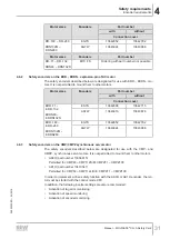
4.2
Encoder cable requirements
4.2.1
Sine/cosine encoder cable
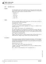
•
Use a shielded encoder cable. Connect the shield at both ends.
•
Max. length of the encoder cable: 100 m
•
Use the prefabricated encoder cables from SEW-EURODRIVE. Observe the fol-
lowing requirements if you use other encoder cables:
– Encoder cable length ≤ 50 m
The cross section of each core of the encoder cable must be ≥ 0.25 mm
2
. The
resistance load per unit length of the cores must not exceed 78 Ω/km (at
20 °C).
– Encoder cable length > 50 m:
The cross section of the cores for the encoder voltage supply and GND must
be ≥ 0.5 mm
2
. The resistance load per unit length of these cores must not ex-
ceed 39 Ω/km. The resistance load per unit length of the signal cores must not
exceed 78 Ω/km (at 20 °C).
24842532/EN – 04/2018

