8
Electrical installation
Safe digital inputs (F-DI.)
Manual – MOVISAFE
®
CS..A Safety Card
47
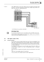
The assignment is made pursuant to the following table: D.
Input terminal
Input pair
Assigned process value
F-DI0
F-DI0/1
F-DI0
F-DI1
F-DI2
F-DI2/3
F-DI2
F-DI3
8.5.1
Discrepancy monitoring
The safety card carries out discrepancy time monitoring for input pairs in the dual-
channel equivalent and dual-channel non-equivalent connection types. The discrep-
ancy time monitoring verifies whether the two input signals are delivering error-free
levels that match the switching state of the sensor. A deviation is tolerated for the
parameterized discrepancy time. An input error occurs if the deviation from the expec-
ted signal state exceeds the discrepancy time. The discrepancy time can be adjusted
for each input pair via a parameter.
The safety card carries out a switch test function for input pairs in the dual-channel
equivalent and dual-channel non-equivalent connection types in order to verify the
connected switch for correct switching behavior following a detected discrepancy
error. The switch test function can be activated and deactivated for each input pair via
a parameter. The switch test function assumes that the switch contacts are moved into
the opened/activated state after the occurrence of the discrepancy error, so that the
two input signals assume the required state for the switch test:
•
Connection type; Dual-channel equivalent
– F-DI. = logical "0"
– F-DI. + 1 = logical "0"
•
Connection type; Dual-channel non-equivalent
– F-DI. = logical "0"
– F-DI. + 1 = logical "1"
Only in this case can the discrepancy error be acknowledged; acknowledgment is oth-
erwise impossible and the input remains in the discrepancy error.
8.5.2
Interlocking
An interlocking function is available for the secure digital inputs. This can be activated
via a parameter with the parameter tool "Assist CS..". The interlocking prevents a
drive safety function activated via the safe digital inputs from being deactivated without
user intervention via the change in input signals from the "0" state to the "1" state. The
interlocking sets the process value of the safe digital input to logical "0" until an ac-
knowledgment has occurred.
The acknowledgment can occur as follows:
•
Via a safe digital input that is parameterized as "Acknowledgment of interlocking
safe digital input".
•
Via a safe digital input that is parameterized as "Acknowledgment of interlocking
safe digital input and error".
•
Via the "Acknowledge F-DI" bit in the safe process output data.
The inputs with active parameterization remain at logical "0" after each activation of
the safety card until an acknowledgment has been carried out.
24842532/EN – 04/2018

